General Information
1-9
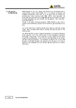
1.11 Emission
measurements
All electric and electronic devices are potential generators of Electro-
Magnetic Interference (EMI).
The term EMI thus refers to the electromagnetic energy emitted by a
device which propagates itself along cables or through the air and couples
with other devices that are present in the surroundings.
These electromagnetic fields (conducted or radiated interferences) may
generate interfering currents and voltages into nearby equipment and
therefore can cause possible malfunctions.
In order to prevent and control such interferences there are nowadays a
number of national and international standards, like IEC and CISPR, which
specifies limits and methods of tests. Moreover, within the European Union
the application of several European Norms on Electromagnetic
Compatibility is enforced by law and therefore the commercialization and
use of all the electric and electronic equipment is subject to the
measurement of the EMC characteristics, which must be within well
defined limits.
The design approach adopted for the PMM FR4003 is that the instrument
shall be innovative, full compliant with all the relevant standards and at the
same time simple and reliable to use, to be the base building block for any
possible emission system to measure and evaluate any electric or
electronic device from the very first design stages to the final certification.
The need to precisely measure the conducted and radiated EMI noises
forces the equipment manufactures to use reliable equipment to verify the
limits imposed by the relevant standards and/or enforced by local rules.
In this view the PMM FR4003 Field Receiver is the ideal solution from
prototype debugging to final certification, as it fully meets all the
performance criteria dictated by these standards, although it remains
small, lightweight and very easy to use.
The PMM FR4003 Utility control software permits an immediate use of the
instrument without any training or special difficulties: the operator can
concentrate just on analyzing the measurement results.
Moreover, the PMM FR4003 software has also been designed for a fast
and easy installation on any PC with the Windows
™
operating system and
with at least one free USB (or Serial Port).
The device under test (DUT) must be installed according to the procedures
indicated in the constructor’s manual and normal operating conditions
respected.
Be sure not to overload PMM FR4003: the input signal should not
exceed the maximum level indicated in the main specifications in
chapter 1.
Also do not apply any signal to the rear RF output connector.
Summary of Contents for PMM FR4003
Page 10: ...X Contents This page has been intentionally left blank...
Page 20: ...1 10 General Information This page has been intentionally left blank...
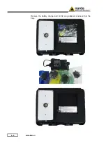
Page 26: ...2 6 Installation Remove the battery charger and all AC plug adapters enclosed into the bag...
Page 32: ...2 12 Installation This page has been left blank intentionally...
Page 82: ...5 12 Utility Calibration and Analog mode This page has been left blank intentionally...
Page 94: ...7 10 Updating Firmware This page has been left blank intentionally...
Page 134: ...10 4 Packaging Instructions Close the carrying case...
Page 138: ...Suggerimenti Commenti Note Suggestions Comments Note...


