background image


Installation 2-11 


2.14 Using Antennas and 
       other Transducers 

In the frequency range from 9 kHz to 30 MHz any other transducer can be 
used to pick-up and measure RF conducted and radiated emissions, like 
active and passive loop antennas, different rod antennas (the rod supplied 
with the unit is already equipped with two lengths, to cover more 
standards), near field probes etc. 
The characteristics of these transducers are usually specified in the 
relevant standards (e.g. Military or Automotive Standards). 
Their use with PMM FR4003 is very easy, as it’s enough to enter their 
response with the frequency into the memory of the receiver to have the 
readings automatically corrected. When the cable is not calibrated together 
with the transducer, even the cable loss can be entered. 


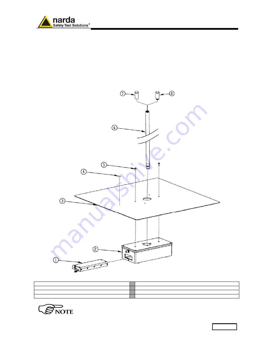
Fig. 2-2

 Antenna parts and assembly 


1 – BP-02 Li-ion battery pack 


5 – n°2 Cylindrical Screws M5x12mm 

2 – FR4003 Field Receiver 


6 – 1000mm Rod 

3 – 600 x 600 mm counterpoise 


7 – Vinyl cap 

4 – Electrostatic charges warning label 


8 – MIL-STD 40mm Rod extension 


To Install the RA-01 on the TR-01 optional accessory see chapter 9 

Summary of Contents for PMM FR4003

Page 1: ...You can find the Serial Number on the front panel of the instrument Serial Number is in the form 0000X00000 The first four digits and the letter are the Serial Number prefix the last five digits are...

Page 2: ...SAFETY SYMBOLS You now own a high quality instrument that will give you many years of reliable service Nevertheless even this product will become obsolete When that time comes please remember that ele...

Page 3: ...Page 1 1 1 1 1 2 1 3 1 3 1 4 1 6 1 7 1 8 1 8 1 9 2 Installation 2 1 Introduction 2 2 Initial Inspection 2 3 Unpacking 2 4 Preparation for Use 2 5 Battery Charger 2 5 1 To replace the mains connector o...

Page 4: ...e 3 3 1 Frequency 3 3 2 RBW 3 3 2 1 Additional RBW Filters 3 3 2 2 MIL STD 461E Activation Procedure option 3 3 3 Level 3 3 3 1 Input Attenuators and Preamplifier 3 3 3 2 OVER RANGE Message 3 3 3 3 Mi...

Page 5: ...1 1 Parameter 4 4 1 2 Detector 4 4 2 Manual Mode Global Test Settings 4 4 2 1 BW IF 4 4 2 2 Attenuator Min Att 4 4 2 3 Over Range 4 4 2 4 Limits 4 4 2 5 Battery 4 4 2 6 Factors 4 4 2 7 HPF and HiZ re...

Page 6: ...te control 8 1 Introduction 8 2 Communication 8 3 Protocol 8 4 Format 8 5 Remote swich on 8 6 Auto switch off 8 7 List of commands 8 7 1 QUERY Commands 8 7 2 SETTING Commands 8 7 3 IDLE Commands 8 7 4...

Page 7: ...peration method Sweep mode screen Analyzer mode window Manual mode window PMM TR01 Wooden Tripod Adjustable joint Column strenghthner Soft carrying case FR4003 parts and assembly Page 1 6 1 7 1 7 1 8...

Page 8: ...shall be provided with fuses or protections rated to the unit Verify that the unit is set to match the available mains voltage and correct fuse rating is installed before applying power The Safety Cl...

Page 9: ...ul Neva SV Italy sulla base delle seguenti norme europee armonizzate applicate con esito positivo based on the following harmonized European Standards successfully applied EMC Emissioni EMC Emission E...

Page 10: ...X Contents This page has been intentionally left blank...

Page 11: ...ccessories checklist to verify all accessories enclosed in the packaging 1 2 Operating Manual Changes Instruments manufactured after the printing of this manual may have a serial number prefix not lis...

Page 12: ...m a self calibration procedure and to check its good operation at any time It is at the same time a traditional active Rod Antenna with a RF analog output and a versatile EMI receiver already internal...

Page 13: ...fiber for PC USB OC Optical Converter Carrying case Reversible screwdriver Operating manual PMM FR4003 Utility Software on Software Media Certificate of Calibration Return for Repair Form 1 5 Optional...

Page 14: ...NL 38 dB V m Hz N input 50 term 1 dB V PK 12 dB V AVG DANL 52 dB V Hz Spurious response 10 dB V Att 0 dB 50 termination AVG Hold time 10 ms RBW auto Measurement accuracy 9 kHz to 30 MHz 0 8 dB Presele...

Page 15: ...l compliant rod antenna FW updating Through the optical link via USB Power supply 7 4 V 7 8 Ah Li Ion rechargeable interchangeable battery 8h avg Operating time 4h avg Charging time 100 240 Vac 50 60...

Page 16: ...enuator has been set to 10 dB it blinks half on and half off when set to 20 dB and it is permanently ON when set to 30 dB PRE Push Button Preamplifier Led indicates the preamplifier status HPF Push Bu...

Page 17: ...t to right A OUT Analog Output BNC female connector 50 Batt Rechargeable Battery PMM BP 02 with charger connector The battery can be easily replaced or charged separately from the unit Power Supply Po...

Page 18: ...ot of the whole band in just one second and using a true built in FFT capability perfectly show the complete band in all its details Later on will be then possible to make the QuasiPeak evaluation of...

Page 19: ...and reliable to use to be the base building block for any possible emission system to measure and evaluate any electric or electronic device from the very first design stages to the final certificatio...

Page 20: ...1 10 General Information This page has been intentionally left blank...

Page 21: ...e shipping cardbox for any damages If the shipping box is damaged it should be kept until the contents of the shipment have been checked for completeness and the instrument has been checked mechanical...

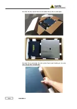
Page 22: ...2 2 Installation Remove the two square foam inserts placed above the counterpoise Remove the counterpoise from its custom foam insert holding on one side do not use the central hole...

Page 23: ...Installation 2 3 Remove the 1000 rod from its custom foam insert Remove the Carrying case from its custom foam insert Place the carrying case on a stable surface...

Page 24: ...carrying case and remove the Operating manual Certificate of Calibration and Packaging Check list Verify the availability of all the shipped items with reference to the Packaging Check list Remove the...

Page 25: ...Installation 2 5 Remove the calibration and counterpoise screw kit the USB OC Optical Converter Software Media and the 40mm rod extension enclosed into the bag...

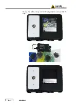
Page 26: ...2 6 Installation Remove the battery charger and all AC plug adapters enclosed into the bag...

Page 27: ...0 mA DC Connector 2 5 1 To replace the mains connector of the battery charger To replace the mains connector simply remove the one installed on the battery charger sliding it off and insert the one th...

Page 28: ...pleted PMM FR4003 is functional as a receiver but it is inadvisable to use it as an antenna for the presence of the power cord which would negate the advantages of the fiber optic connection and may b...

Page 29: ...thinner turpentine acid acetone or similar matter to avoid damage to external plastic surfaces 2 9 Equipment ventilation To allow correct equipment ventilation ensure that the instrument is operated w...

Page 30: ...amage the input circuitry The pulse limiter shall be used only as a protection of the input from unexpected pulses When using an external Artificial Mains Network to reduce the probability of damages...

Page 31: ...the relevant standards e g Military or Automotive Standards Their use with PMM FR4003 is very easy as it s enough to enter their response with the frequency into the memory of the receiver to have the...

Page 32: ...2 12 Installation This page has been left blank intentionally...

Page 33: ...hy made possible only in the recent years by the availability of superior technology components This equipment is fully digital but the input preselector and attenuator and of course the output stage...

Page 34: ...related to the resolution bias error that may cause in an FFT spectrum the peaks to be measured too low and the valleys too high in level This phenomenon is avoided by adding a certain number of over...

Page 35: ...operating mode all the relevant information are reported on the screen From the upper left corner the User can see if the Preselector is ON or OFF if the Preamplifier is ON or OFF which detector is i...

Page 36: ...r will be set to scan the 0 15 30 MHz frequency band The definition of band B is a given in CISPR Pressing A B Band the receiver will be set to scan the entire band from 9 kHz to 30 MHz In this way th...

Page 37: ...arning status The Min Att button acts as a toggle switch it selects the minimum attenuation among 0 10 20 and 30 dB When a minimum attenuation is selected the attenuator doesn t matter if in automatic...

Page 38: ...nerator menu 3 2 1 5 RF Output Generator The RF Output generator is an internal high stability and accuracy 50 Ohm RF generator ranging from 9 kHz to 30 MHz NOTE Due to the Ultra Fast FFT technology o...

Page 39: ...e lower than the allowed is entered the lowest possible value is automatically selected The max Hold Time that can be set is 120 sec The C RMS CISPR RMS Average detector is a payment special function...

Page 40: ...e one limit with a simple push of a button The preloaded standard limits refer to the most popular EMC emission standards CISPR22 CISPR14 and CISPR11 Other limits or any custom designed limit can be c...

Page 41: ...possible to quickly move on markers from higher amplitude left arrow to lower amplitude right arrow i e if the highest is selected pressing the right arrow key the 2nd highest is selected then pressi...

Page 42: ...ease note that the Load function is scanning the memory in a circular way therefore all the occupied memory positions are shown in sequence When the key shows Load 4 it means the trace 3 is displayed...

Page 43: ...OFF if the Preamplifier is ON or OFF which detector is in use and the relevant hold time if the input attenuation is Automatic or Manual and the set attenuation and if the Minimum attenuation is 10 dB...

Page 44: ...ore enough to edit the value with the soft keys and the left and right arrows confirming the selections entering the units value kHz MHz or GHz The figures entered appear in a small window just below...

Page 45: ...required by the standards More filters will be available for specific applications e g to cover Military Standards requirements etc 10 Hz MIL at 6dB Option 100 Hz MIL at 6dB Option 1 kHz MIL at 6dB 3...

Page 46: ...hapter Click on 9010 Set code Utility WRDONGLE EXE once for running the Set code program so getting the following window Copy the 40 Digit Serial Code in the Dongle Code Window and select the Write MI...

Page 47: ...the receiver in manual attenuation When the input attenuation is 0dB condition that can be achieved only if the Minimum Attenuation is set to 0 dB as well the yellow led to the left of the input BNC...

Page 48: ...he Miscellanea functions menu it is possible to activate or exclude the Preselector filters and also to set the Signal Generator The Preselector is composed by a group of filters automatically selecte...

Page 49: ...select the most appropriate detector for the test In Analyzer mode the Peak Average and RMS Root Mean Square detectors are available and can be selected via the appropriate button Hold time The Hold...

Page 50: ...factor and NONE to unload it 3 3 4 Marker With this command the Marker function can be enabled Switching ON the marker it appears on the screen as a small black pointing down arrow and simultaneously...

Page 51: ...ode function has five sub windows Frequency Level Resolution Bandwidth Hold Time Demodulation Always use Esc button to return to the previous view condition 3 5 2 MIL Filters The Resolution Bandwidth...

Page 52: ...ituation the Hold Time value should be manually set to find a correct compromise To set the Hold Time to the lowest possible value this value dynamically depends from the measurement conditions enter...

Page 53: ...g the receiver in the selected method Fig 4 1 Operation method 4 2 Sweep mode To switch into the Sweep Mode simply select the proper Sweep Tab Entering in the new operating mode the main screen will l...

Page 54: ...ed to set the steps of the Sweep it includes Step Hz if AUTO is active the frequency steps are set automatically for best matching with RBW filters in the selected frequency range Otherwise the step c...

Page 55: ...e incoming signal and to measure it with the chosen detector at each tuned frequency When selecting a detector the default hold time value is automatically loaded but in some cases this time is not ap...

Page 56: ...cted is 0 10 20 or 30 dB When the input attenuation is 0 dB in the PMM Receiver condition that can be achieved only if the Minimum Attenuation is set to 0 dB as well the yellow led named ATT blinks ra...

Page 57: ...at the end of the test the software retains and displays the maximum measured level at each frequency as Envelope while every sweep will always be maintained for deeper investigation on the most noisy...

Page 58: ...ment with button Execute Once the scan starts the button Execute toggles on a Battery status box When the battery is charging the status Charging is shown on the inside of the battery symbol and a yel...

Page 59: ...he Analyzer Mode simply select the proper Analyzer Tab After that you can start defining the settings included in the Analyzer Tab and in the Global Test Settings 4 3 1 Introduction The display shows...

Page 60: ...2 2 Frequency Allows the User to set the tuning frequency and also the Span Using the Start and Stop it is possible to select any start and stop value in the frequency range Another method for setting...

Page 61: ...00 Hz CISPR 16 shaped at 6dB 9 kHz CISPR 16 shaped at 6dB 1 kHz MIL STD 3 kHz 10 kHz MIL STD 30 kHz 100 kHz 300 kHz If Coupled is active the Resolution Bandwidth will be set automatically in order to...

Page 62: ...oth for the 100 cm and for the 104 cm rods To activate the desired factor scroll the drop down menu select the proper file and tick the corresponding box On the right the program shows the actual corr...

Page 63: ...ode window In manual mode the levels corresponding to the detectors in use are displayed both in analogue and in digital format and exactly as for the other operating modes all the relevant informatio...

Page 64: ...asing the value or the input attenuators However when the input attenuation is set the signal is gone so the receiver lowers the attenuation but then a new peak arrives and so on and so forth On the o...

Page 65: ...t Min Att The attenuator Att is used to increase or decrease the attenuation at the input it cannot be lowered than the value of the minimum attenuation Min Att selected the value selected will be sho...

Page 66: ...e value is displayed and the length of the bar filling the symbol indicates the available autonomy 4 4 2 6 Factors Geometrical antenna factors for FR4003 are preloaded during the PMM Emission Suite in...

Page 67: ...ime associated to the detectors in use if the input attenuation is Automatic or Manual and the set attenuation and if the Minimum attenuation is 10 dB or 0dB if there a demodulation and the level of t...

Page 68: ...KG The RMS Average detector according to the CISPR 16 1 1 standard supplies a reading of the input signal that is weighted for repeated pulses such that for a constant indication the relationship bet...

Page 69: ...ngle Code Window and select the Write RMS AVG Dongle button This message appears when the Dongle code is not valid It will be shown the following message press OK to confirm The software will inform t...

Page 70: ...oad PMM FR4003 the input signal should not exceed the maximum level indicated in the main specifications in chapter 1 Also do not apply any signal to RF output connector After the activation the RMS A...

Page 71: ...lity software is the tool to set the Rod Antenna parameters when used in analog mode without taking advantage of the internal receiver It is also useful to perform the autocalibration of the antenna i...

Page 72: ...ing the provided USB optical converter and the plastic optic fiber The cover screen appears showing two buttons one to connect to the Field Receiver and the other to exit 5 1 1 Connection Press the Co...

Page 73: ...menu there are the buttons useful to switch the Field Receiver off and to exit the program 5 1 2 Preferences The program language can be chosen under the preferences menu 5 1 3 Tools The Tools menu in...

Page 74: ...e intrinsec capacitance of the Rod or any other transducer connected to the N input In the Cap measure box select the Monopole radio button to exclude the parasitic capacitance due to the input connec...

Page 75: ...Utility Calibration and Analog mode 5 5 A message pops up asking for the confirmation if the User is sure about running the calibration procedure...

Page 76: ...ibrator box then wait again for the measurement is taken 4 When the Calibrator text becomes black connect the 15 pF fixture Fixture and click the Fixture box then wait again for the measurement is tak...

Page 77: ...un the Auto Calibration simply click onto the corresponding icon The following window appears Then please click Start auto calibration If the Rod antenna or anything else is connected to the N input t...

Page 78: ...uple of minutes to complete The resulting tabled values are the calibration factors the User needs to adopt when using the antenna in Analog mode 5 1 4 Information Clicking the desired icon it is poss...

Page 79: ...also available and displayed in degrees Celsius Clicking onto the information icon the following useful window appears showing the versions of all the softwares and firmwares This function is very hel...

Page 80: ...at the instrument can be operated stand alone as for the controller simply unconnecting the PC since the settings are mantained The screen below shows a typical setting for an analog mode usage with P...

Page 81: ...for a few seconds to switch off the unit The ON OFF status is indicated by the corresponding Led lamp ATT Press this button to select the desired output attenuation Led Off 0 dB Fast blink 10 dB Slow...

Page 82: ...5 12 Utility Calibration and Analog mode This page has been left blank intentionally...

Page 83: ...st be added to antenna factor when electric field strength is measured In the meantime this length corresponds to a 1 8 wavelength at the frequency of about 37MHz so it is possible to use it up to mor...

Page 84: ...ertheless the most common tests in the frequency range covered by PMM FR4003 are certainly the conducted measurements done with the help of a Rod antenna or a LISN Selecting the HiZ High impedance rec...

Page 85: ...the program or application as an administrator until close it Windows also allows to mark an application so that it always runs with administrator rights 7 3 Preparing the Hardware Turn off the PMM FR...

Page 86: ...7 2 Updating Firmware Run the FR4003SeriesUp Setup Then please follow the on screen indications...

Page 87: ...mission Suite from where the FR4003SeriesUp and WrDongle programs can be easily run To obtain firmware or software updates for FR4003 please contact your NARDA distributor or download it directly from...

Page 88: ...Firmware which is the receiver internal program FPGA swept method to update the internal programmable logic and FPGA FFT method to update the internal programmable logic The FR4003FW LDR file required...

Page 89: ...stop before reaching the 100 completion that will have not to be considered a trouble but simply an intermediate step in this case please switch OFF and ON the receiver and repeat the FW Upgrade proce...

Page 90: ...l the automatic transfer is completed During the firmware storing procedure a blue bar will progress from left to right in the window of the PC showing percentage of downloading time by time until 100...

Page 91: ...ease should not comply with what expected just check about the FW file used during installation or get in contact with the nearest NARDA Local Distributor It is now possible to disconnect the cable co...

Page 92: ...e USB port of the PC Browse for All Programs from the Start Menu and reach the WrDongle executable link Main window displayed after the program WrDongle has been run Select USB or RS232 communication...

Page 93: ...ode to the Dongle Code input field and press the button below related to the specific Option In case of failure an error message is showed instead Always cycle OFF and ON the receiver to properly init...

Page 94: ...7 10 Updating Firmware This page has been left blank intentionally...

Page 95: ...n and set to 0 during transmission Every string starts with the special character and stops with 8 4 Format Commands are made of ASCII string delimited character 0x23 and the character 0x2A Replies ar...

Page 96: ...Attenuator status for Manual mode MHT Requests the Hold Time for manual mode MIL Sends back a string telling whether MIL Filters are available MPA Sends back a string expressing the Preamplifier stat...

Page 97: ...d making it active or deactivating it SLII n Recall and load into FR4003 the built in limit indexed by n SLIM n Sets the Margin to be used with Smart Detector function SLIW n freq lev Sets the custom...

Page 98: ...as follows IPS index where index is IRO Sends back a string expressing current RF OUT to BNC connector status ITG sends back a string expressing the current internal Tracking Generator to the mode st...

Page 99: ...er mode is 1000ms or 1s AOP This query command AOP sends back a string expressing the Stop frequency in exponential notation for analyzer mode Unit is fixed MHz Example of reply AOP 3 000000e 07 which...

Page 100: ...or as shown in FR4003 menu and LABEL is its temporary name as it was last labelled If No conversion factor is active the reply is CFA NONE Example of reply CFA 1 PROBE means that conversion factor 1 i...

Page 101: ...ed ms Example of reply MHT 1000 ms which means that the hold time in manual mode is 1000ms or 1s MIL This query command MIL sends back a string telling whether MIL Filters are available Reply is MIL N...

Page 102: ...SHT This query command SHT sends back a string expressing the HOLD TIME for Sweep mode Unit is fixed ms Example of reply SHT 1000 ms which means that the hold time in Sweep mode is 1000ms or 1s Note t...

Page 103: ...Generator when is not tracking is 15MHz TGL This query command TGL sends back a string expressing the output level of FR4003 Built In Generator Unit is fixed dB V Example of reply TGL 90 0 which mean...

Page 104: ...3 restarts sending diagnostic messages which end with CHGS OK this is procedure take about 4 seconds The Remote LED blinks fastly Note Once switched OFF the PMM FR4003 returns to FFT method SA30A SA30...

Page 105: ...Analyzer mode SAGO This setting command puts the FR4003 in Analyzer mode The reply is always SAGO OK which acknowledges the command has been granted followed by an array variable in size representing...

Page 106: ...uency for Analyzer mode to 150kHz SCFA n This setting command activates the conversion factor stored in the FR4003 if any where n is the ID of the conversion factor If n is not in the range 1 to 4 no...

Page 107: ...0 Send the second line 500kHz 0 dB SFCW 2 1e6 1 2 Send the third line 1MHz 2 dB SFCW 3 2e6 1 1 Send the fourth line 2MHz 1 1 dB SFCW 4 30e6 1 Send the fifth line 30MHz 1 dB SCFE 2 Probe Save it perman...

Page 108: ...2 5e6 56 46 Send the third line 5MHz 56 dB V SLDW 3 5e6 60 50 Send the fourth line 5MHz 60 dB V SLDW 4 30e6 60 50 Send the fifth line 30MHz 60 dB V SLIE Custom Double Send the name and make the limit...

Page 109: ...sly loaded by SLIW commands names the limit as Custom Limit and activates it Example SLIE deactivates any limits SLII n This setting command recall and load into FR4003 the built in limit indexed by n...

Page 110: ...must be made in upwards order otherwise all point having a higher index previously written are cleared It is responsibility of the user to make sure the data sent are correct and coherent The reply is...

Page 111: ...The reply is MPA OK which acknowledges the command has been granted or MPA SERR if the command has been ignored When the command is granted the FR4003 goes to manual mode automatically Example SMPA O...

Page 112: ...ne and available for uploading by the command FSF 0 NOTE that all setting commands are ignored while the sweep is on while query commands are granted as well as the command ASBK which allows aborting...

Page 113: ...rs set will be measured and sent out However in Smart Mode only one detector at time in addition to PEAK which is always present can be set o Non Smart Mode All detectors can be indicated at once Orde...

Page 114: ...ee sweep no automatic items are selected based on the provided parameters After this command has been received all parameters issued in the command itself are checked out and if coherent a sweep start...

Page 115: ...sitive SFD ERR 8 RC LF An Error was found in Preselector string Preselector string can be either ON or OFF only String is not case sensitive Once the sweep is started the FR4003 sends the value of eac...

Page 116: ...be the minimum suitable automatically adjusted by the unit RBW is 9kHz MinAtt is 10 dB which means that the attenuator will not switch below 10 dB attenuation Preamplifier is OFF while the Preselecto...

Page 117: ...he user to make sure the data sent are correct and coherent The reply is SSFW OK which acknowledges the command has been granted or SSFW SERR if the command has been ignored SSHT h This setting comman...

Page 118: ...be in exponential form and should be expressed in Hz Frequency should range between 9 kHz and 30 MHz inclusive The reply is TGF OK which acknowledges the command has been granted or TGF SERR if the co...

Page 119: ...ttenuator 150kHz is enabled ICM This query command ICM sends back a string expressing current CAP METER status The reply is either ICM Off The CAP METER is ON ICM On The CAP METER is OFF IHP This quer...

Page 120: ...or 9kHz SIAT a This setting command immediately sets Attenuator to the value indicated by a can range 0 to 30 in step of 10 The reply is IAT OK which acknowledges the command has been granted or IAT S...

Page 121: ...which can be either On or OFF The reply is IRO OK which acknowledges the command has been granted or IRO SERR if the command has been ignored Example SIROON The output has been switched to BNC Connect...

Page 122: ...the hold time to 2 ms SADT 2 Sets the detector to AVG More Command More Command SAGO Start Sweep in Analyzer Mode The PMM FR4003 replies by sending a 48 bytes header followed by a variable size array...

Page 123: ...Fstart 2 Fstep Little Endian 16 bit integer representing the level referred to start frequency plus 2 step frequency 52 nn Level Fstop Little Endian 16 bit integer representing the level referred to...

Page 124: ...s the sweep data are contained in the header the fact that the step used is different from the FR4003 does not affect the interpretation of the data that remains the same Sweep Mode With SSFD command...

Page 125: ...of the following conditions Temperature Humidity without condensation From 30 C to 75 C 98 relative 9 4 Return for repair When the Accessories need to be returned to NARDA for repair please complete t...

Page 126: ...PMM TR 01 Wooden tripod with extension Specifications Characteristics Performance Limits Legs Transportation width Minimum height Maximum height Weight Load capacity 3 legs x 3 sections extensible 76...

Page 127: ...mm 184 g 10 kg The Column strenghthner allows to mount the FR4003 on the PMM TR 01 Wooden tripod with extension Fig 9 3 Column strenghthner TABLE 9 3 Soft carrying case Specifications Dimensions 160 x...

Page 128: ...9 4 Accessories 9 6 2 FR4003 installation on TR 01A Wooden tripod Fig 9 5 FR4003 parts and assembly Legend 1 FR4003 2 Column strengthener 3 PMM TR01 Wooden Tripod...

Page 129: ...Accessories 9 5 Unscrew the pan head screw from Column strengthener without losing it completely Screw the Column strengthener on the FR4003 bottom be sure that it is well locking...

Page 130: ...ing it completely from the TR 01 Install the PMM TR 01 Wooden Tripod on the site Insert the Column strengthener fixed to FR4003 on the wooden extension and make sure it is fully inserted then screw th...

Page 131: ...re sensitive to mechanical shocks as well as heavy ones like the counterpoise It is therefore suggested to follow carefully the packing instructions to avoid damages due to the shipment 10 2 Packaging...

Page 132: ...all AC plug adapters into the bag and place it into the carrying case as shown Insert the calibration and counterpoise screw kit the USB OC Optical Converter the 40mm rod extension and Software Media...

Page 133: ...ckaging Instructions 10 3 Place the 9010F and PC fiber optic into the carrying case as show Place the Operating manual Certificate of Calibration and Packaging Check list into the carrying case as sho...

Page 134: ...10 4 Packaging Instructions Close the carrying case...

Page 135: ...Instructions 10 5 Place the carrying case on its custom foam insert Place the 1000 Rod on its custom foam insert Place the counterpoise on its custom foam insert holding on one side do not use the cen...

Page 136: ...10 6 Packaging Instructions Place the two square foam inserts above the counterpoise and cover all items with the rectangular one Close the box with packaging tape...

Page 137: ...n you would like to submit to the attention of our service organization is kept in great consideration Moreover we are continuously improving our quality but we know this is a never ending process We...

Page 138: ...Suggerimenti Commenti Note Suggestions Comments Note...

Reviews: