9010F Fast
3-7
3.2.1.6 Detector
This menu allows the operator to select the most appropriate
detector
for
the test.
In Sweep mode the Peak, Average, RMS (Root Mean Square) and Quasi-
Peak detectors are available, and can be selected, via the appropriate
button.
Hold time (ms)
The Hold Time (expressed in milliseconds) represents the time the receiver
uses to “take a snapshot” of the incoming signal and to measure it with the
chosen detector. When selecting a detector, the default hold time value is
automatically loaded. In some cases e.g. when the interference signals have
a low repetition rate setting a longer Hold Time may be necessary for
preventing the auto-attenuator to continuously switching up and down
To set the
Hold Time
to the lowest possible value (this value dynamically
depends from the measurement conditions), enter the figure 0; if a value
lower than the allowed is entered, the lowest possible value is automatically
selected.
The max.
Hold Time
that can be set is 120 sec.
The C-RMS (CISPR RMS-Average) detector is a payment special
function implemented in the PMM 9010F receiver.
RMS-Average detector is manufactured under license of Rohde & Schwarz
GmbH & Co. KG.
The RMS-Average detector, according to the CISPR 16-1-1 standard,
supplies a reading of the input signal that is weighted, for repeated pulses,
such that for a constant indication, the relationship between amplitude and
repetition frequency is in accordance with the following rule:
the Amplitude is proportional to (repetition frequency)-1/2
The value is the maximum level during the measurement time (Hold Time)
and the averaging is carried out with a lowpass filter of the 2
nd
order to
simulate a mechanical instrument.
The calibration is in reference to the RMS value of an unmodulated
sinewave signal.
To enable the RMS-AVG Detector, use the 9010 Set code Utility.
Please refer to the 9010F User’s Manual for any further information.
Summary of Contents for PMM FR4003
Page 10: ...X Contents This page has been intentionally left blank...
Page 20: ...1 10 General Information This page has been intentionally left blank...
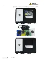
Page 26: ...2 6 Installation Remove the battery charger and all AC plug adapters enclosed into the bag...
Page 32: ...2 12 Installation This page has been left blank intentionally...
Page 82: ...5 12 Utility Calibration and Analog mode This page has been left blank intentionally...
Page 94: ...7 10 Updating Firmware This page has been left blank intentionally...
Page 134: ...10 4 Packaging Instructions Close the carrying case...
Page 138: ...Suggerimenti Commenti Note Suggestions Comments Note...


