background image

English

18

Protective guard

Attention! The protective guard intended only and ex-

clusively for work with the grinding wheels is the inte-

gral part of the standard angular grinder outfit.

When cutting, the angular grinder has to be equipped by the pro-

tective guard intended for work with the cutting wheels; it can be 

purchased in the trade network under the order No. 00 763 301 for 

dia. 125 mm. Failing to use the guard for cutting, you run the in-

creased risk of injury and in this case (non-use of the special guard 

for cutting) the company Narex is not liable anyhow for possible 

harm of health of the user or another person injured as the conse-

quence of breach of the safety rules.

Put the protective guard (8a; 8b) on the clamping collet (6). The guide 

lugs (9) must be inserted into the grooves on the clamping collet. Set 

the protective guard (8a; 8b) to the requested working position.

Note: The protective guard has been designed so that no tool may 

be needed for fixing the protective guard in the requested working 

position.

Attention! For safety reasons the clamping bolt (10) has been 

tightened in the manufacturing plant by the torque 3.5 Nm so 

that the safety guard may not be loose on the clamping col-

let (6), but may be swiveled by hand after overcoming the set 

resistance.

 It is necessary to check the mounted protective guard 

- it may not be loose (may not wobble) on the clamping collet. 

For possible tightening the clamping bolt (10) use the hexagonal 

wrench dia. 4 mm (18) and check the torque 3.5 Nm.

Additional handle SOFTGRIP

The additional handle (17) can be screwed from the left or right 

gearbox (5) side or from the top gearbox (5) part. Thanks to the 

special design vibrations are reduced by the additional handle (17).

Grinding or cutting wheel fixing

Attention! Prior to handling the accessories, the pow-

er supply cable has always to be disconnected from 

the power source socket!

Mounting with the standard clamping nut

Clean the bottom flange (11) and the clamping nut (14a) as well as 

the clamping surfaces of the grinding or cutting wheel. Place the 

bottom flange (11) (by the recess out) on the spindle (7). Place the 

grinding (12) or cutting wheel (13). The bottom flange recess (11) 

must be inserted precisely into the grinding wheel (12) or the cut-

ting wheel (13) hole. Then put the clamping nut (14a) on the spin-

dle (7) so that when fixing the grinding wheel (12), the clamping 

nut recess (15) must be faced towards the wheel and when fixing 

the cutting wheel (13), the clamping nut recess (15) must be di-

rected from the wheel!

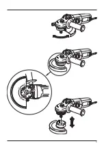
Depress the lock spindle pin (3).

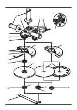
Description of the device

1 ...........Switch 

2 ...........Vent holes

3 ...........Lock spindle pin

4 ...........Revolutions pre-setting

5 ...........Gearbox

6 ...........Clamping collet

7 ...........Spindle

8a .........Protective guard for grinding

8b .........Protective guard for cutting

9 ...........Guide lugs

10 .........Clamping bolt

11 .........Bottom flange

12 .........Grinding wheel

13 .........Cutting wheel

14a .......Clamping nut

14b ......Quick-clamping nut

15 .........Clamping nut recess

16 .........Wrench

17 .........Additional handle

18 .........Hexagonal wrench dia. 4 mm

19 .........Securing lever

Depicted or displayed accessories need not necessarily become 

the integral part of delivery.

Double insulation

To ensure maximum safety of the user, our tools are designed and 

built to satisfy applicable European standards (EN standards). Tools 

with double insulation are marked by the international symbol of 

a double square. These tools must not be grounded and a two-wire 

cable is sufficient to supply them with power. Tools are shielded in 

accordance with EN 55014.

Use

The machine is designed for splitting, roughing and brushing met-

al and stone materials without the use of water. For cutting stone, 

a cutting guide is required.

The user himself is liable for any improper use.

Protective elements and their 

assembly 

The grinder may be used with mounted protective guard only!

Attention! Prior to handling the accessories, the pow-

er supply cable has always to be disconnected from 

the power source socket!

Technical Specification

Angular grinder

Model 

EBU 13-12 C 

EBU 13-14 C 

EBU 13-14 CE

Voltage 

(V) 

230–240 230–240 230–240

Mains frequency (Hz) 

50–60 

50–60 

50–60

Power input (W) 

1 200 

1 400 

1 400

Idle speed (rpm) 

10 500 

11 000 

3 500–11 000

Grinding/cutting wheel dia. max. (mm) 

125 

125 

125

Additional handle SOFTGRIP 


Circumferential speed (m/s) 

80 

80 

80

Work spindle thread 

M 14 

M 14 

M 14

Limits to interaction current 


Revolutions pre-setting 


Constant electronics 


Heat protection 


Weight without tool (kg) 

2.0 

2.1 

2.3

Class of protection 

II /   

II /   

II / 

Summary of Contents for EBU 13-12 C

Page 1: ...k pou v n P vodn n vod na pou itie Original operating manual Originalbetriebsanleitung Instrucciones de uso originales p Pierwotna instrukcja obs ugi Eredeti haszn lati tmutat EBU 13 12 C EBU 13 14 C...

Page 2: ...ie Risikoreduzierung die Anleitung Cuidado Lea las instrucciones para reducir los riesgos de que se produzcan da os Uwaga Dla zmniejszenia ryzyka urazu nale y przeczyta niniejsz instrukcj Figyelem A v...

Page 3: ...3...

Page 4: ...4 1 2 6 5 7 9 10 12 13 14a 14b 19 15 18 11 14a 16 8a 8b 4 3 17...

Page 5: ...5...

Page 6: ...4 Pou v n elektrick ho n ad a p e o n a Nep et ujte elektrick n ad Pou vejte spr vn n ad kter je ur en pro prov d nou pr ci Spr vn elektrick n ad bude l pe a bezpe n ji vykon vat pr ci pro kterou bylo...

Page 7: ...z vislosti na pou it pou vejte obli ejov t t bezpe nostn ochrann br le nebo bezpe nostn br le V p im en m rozsahu pou vejte prachovou masku chr ni e u rukavice a pracovn z st ru schopnou zadr et mal...

Page 8: ...P P davn dr adlo 17 je mo no na roubovat z lev nebo z prav strany p evodov sk n 5 nebo z horn strany p evodov sk n 5 Pomoci speci ln konstrukce se vibrace p davn m dr a dlem 17 redukuj Up n n brusn ho...

Page 9: ...kotou i a na opra cov van m materi lu Konstantn elektronika Konstantn elektronika udr uje ot ky p i chodu napr zdno a p i zat en na p ibli n stejn konstantn hodnot T m se doc l rov nom rn pracovn posu...

Page 10: ...dB A POZOR P i pr ci vznik hluk Pou vejte ochranu sluchu V en hodnota vibrac p sob c na ruce a pa e ah AG 4 m s 2 Nep esnost m en K 1 5 m s 2 Uveden hodnoty vibrac a hlu nosti byly zm eny podle zku e...

Page 11: ...starostlivos o neho a Nepre a ujte elektrick n radie Pou vajte spr vne n radie kto r je ur en pre vykon van pr cu Spr vne elektrick n radie bude lep ie a bezpe nej ie vykon va pr cu pre ktor bolo kon...

Page 12: ...t t bezpe nostn ochrann okuliare alebo bez pe nostn okuliare V primeranom rozsahu pou vajte prachov masku chr ni e u rukavice a pracovn z steru schopn zadr a mal lomky brusiva alebo obrobku Ochrana o...

Page 13: ...n naskrutkova z avej alebo z pra vej strany prevodovej skrine 5 alebo z hornej strany prevodovej skrine 5 Pomocou peci lnej kon trukcie sa vibr cie pr davnou rukov ou 17 redukuj Up nanie br sneho aleb...

Page 14: ...an po et ot ok je z visl od pou it ho br sneho kot a a spracov van ho materi lu Kon tantn elektronika Kon tantn elektronika udr uje ot ky pri chode napr zdno a pri za a en bl zko kon tantnej hodnoty T...

Page 15: ...k hluk Pou vajte ochranu sluchu V en hodnota vibr ci p sobiacich na ruky a pa e ah AG 4 m s 2 Nepresnos meran K 1 5 m s 2 Uveden hodnoty vibr ci a hlu nosti boli zmeran pod a sk ob n ch podmienok uved...

Page 16: ...not al low persons unfamiliar with the power tool or these instructions to operate the power tool Power tools are dangerous in the hands of untrained users e Maintain power tools Check for misalignmen...

Page 17: ...ssories that require liquid coolants Using water or other liquid coolants may result in electrocution or shock Kickback and Related Warnings Kickback is a sudden reaction to a pinched or snagged rotat...

Page 18: ...Place the grinding 12 or cutting wheel 13 The bottom flange recess 11 must be inserted precisely into the grinding wheel 12 or the cut ting wheel 13 hole Then put the clamping nut 14a on the spin dle...

Page 19: ...tant Regular operating shift is achieved Protection from overloading dependant on temperature The safety electronics switches to cooling regime when the critical temperature is reached Motor continues...

Page 20: ...ION Noise is generated during work Use ear protection The weighted value of vibrations affecting hands and arms ah AG 4 m s 2 In accuracy of measurements K 1 5 m s 2 The emission values specified vibr...

Page 21: ...s befestigt bleibt kann Personen verletzen e Arbeiten Sie immer nur dort wohin Sie sicher langen k nnen Halten Sie immer eine stabile Stellung und das Gleichgewicht Sie k nnen dann das elektrische Wer...

Page 22: ...das elektromecha sein wie die auf dem Werkzeug angef hrten maximalen Dreh zahlen Ein Zubeh r das in h heren Drehzahlen arbeitet als seine Nenndrehzahlen sind kann brechen und auseinanderfallen e Der...

Page 23: ...us dem Schnitt herauszuziehen wenn die Scheibe sich bewegt ansonsten kann es zu einem R ckschlag kommen berpr fen Sie die Situation und schaffen eine Abhilfe da mit das Verklemmen der Scheibe vermiede...

Page 24: ...if Schneid scheibe 12 13 die Schleifspindel 7 bis der Verriegelungs bolzen 3 einrastet Ziehen Sie die Spannmutter 14a mit dem Schl ssel 16 fest Achtung berpr fen Sie vor dem Einschalten der Ma schine...

Page 25: ...Temperaturschwankung verhindert wird Entsorgung Die Elektrowerkzeuge das Zubeh r und Verpackungen sollten zu einer erneuten Verwertung welche die Umwelt nicht besch digt abgegeben werden Nur f r EU L...

Page 26: ...y el cabello largo pue den ser atrapados por las partes m viles g Si se disponen de medios para conectar equipos de extracci n y recogida de polvo cerci rese de que stos est n bien conectados y de us...

Page 27: ...est n agrietadas desgarradas o extremadamente gasta das y si los cepillos de hierro tienen los alambres flojos o partidos Si el accesorio o la herramienta se caen rev selos o monte un acce sorio no d...

Page 28: ...ructura de la cubierta protectora ha sido dise ada de manera tal que al regular la cubierta protectora y ponerla en la posici n requerida no haya que utilizar ning n instrumento para fijarla en la pos...

Page 29: ...star bloqueado el husillo la tuerca de reacci n r pida Qick action nut 14b puede ajustares s lo manualmente Cuidado Se prohibe ajustar la tuerca de reacci n r pida Qick action nut sin el disco Peligro...

Page 30: ...g n la Directiva europea 2002 96 CE sobre residuos de aparatos el ctricos y electr nicos y su transposici n en las leyes nacionales las herramientas el ctricas desmanteladas inutilizables deben reunir...

Page 31: ...31 1 2 a RCD RCD 3 a 4 a 5 a...

Page 32: ...o 32 a a...

Page 33: ...33...

Page 34: ...55014 00 763 301 125 NAREX 8a 8b 6 9 8a 8b 10 3 5 6 10 4 18 3 5 SOFTGRIP 17 5 5 17 EBU 13 12 C EBU 13 14 C EBU 13 14 CE 230 240 230 240 230 240 50 60 50 60 50 60 1 200 1 400 1 400 1 10 500 11 000 3 50...

Page 35: ...35 11 14a 11 7 12 13 11 12 13 14a 7 12 15 13 15 3 3 3 14 16 11 14a 14b 11 14b 230 220 240 1 1 1 1 16 EBU 13 14 CE 4 1 3 500 1 2 4 600 1 3 6 000 1 4 7 600 1 5 8 900 1 6 11 000 min 1 10 20 80 1...

Page 36: ...2002 96 ES 12 24 NAREX 60745 LpA 90 A LwA 103 A K 3 A ah AG 4 2 K 1 5 2 EN 60745 60745 1 60745 2 3 2006 42 EC 55014 1 55014 2 61000 3 2 61000 3 3 2004 108 EC 2013 Narex s r o Chel ick ho 1932 Anton n...

Page 37: ...si stosownie Nie u ywajcie lu nych ubra ani bi ute rii Dbajcie o to aby wasze w osy ubranie i r kawice by y dosta tecznie daleko od poruszaj cych si cz ci Lu ne ubrania bi uteria i d ugie w osy mog zo...

Page 38: ...rzeni kaj ca tarcza mo e przeci rury z wod lub gazem przewody elek tryczne lub przedmioty kt re mog spowodowa odbicie wsteczne f Rozmiary mocuj ce tarcz ko nierzy p ytek oporowych lub jakich kolwiek p...

Page 39: ...Konstrukcja os ony ochronnej jest tak zaprojektowana aby podczas ustawiania os ony ochronnej do po danej pozycji nie by o u ywane adne narz dzie do jej ustalenia w po danej pozycji Opis maszyny 1 Przy...

Page 40: ...przesun przez naci ni cie palca do przo du przez to maszyna si w czy Je eli b dziecie naciska na przed ni cz przycisku wy cznika 1 dojdzie do zablokowania wy cznika w za czonej pozycji Wy czanie Prze...

Page 41: ...rmin gwarancji wynosi 24 miesi ce w przypadku wy cznie prywatnego u ywania potwierdzone faktur lub kwitem dostawy Szkody wynikaj ce z naturalnego zu ycia przeci ania niepra wid owego obchodzenia si ew...

Page 42: ...n gy jobban oda tud figyelni a k ziszersz mmal v gzett munk ra a v ratlan helyze tekben is f Viseljen megfelel munkaruh t Forg g pek haszn lata eset n kszereket laza ruh t viselni tilos gyeljen arra h...

Page 43: ...t ellen rizze a s r l st vagy szereljen fel nem s r lt tartoz kot Ellen rz s s a tartoz k fel szerel se ut n lljon gy hogy n vagy m s szem lyek a forg tartoz k egyenes n k v l lljanak s engedje a szer...

Page 44: ...d fedelet ellen rizni kell nincs e szabadon a r gz t nyakon nem mozog hat Megh z s eset n haszn ljon csavart 10 hat l kulcsot 4mm 18 s ellen rizze a 3 5 Nm megh z si nyomat kot P t markolat SOFTGRIP...

Page 45: ...kell kapcsolni Fordulatsz m el v laszt EBU 13 14 CE A fordulatsz m el v laszt gombbal 4 el re be lehet ll tani a g p fordulatsz m t 1 3 500 1 perc 2 4 600 1 perc 3 6 000 1 perc 4 7 600 1 perc 5 8 900...

Page 46: ...rizze meg A garanci ra mindig az adott pillanatban rv nyes gy rt i garanci lis felt telek az ir nyad ak Zajszint s vibr ci t j koztat Az rt keket az EN 60745 szabv ny szerint m rt k meg Zajnyom s szi...

Page 47: ...47...

Page 48: ...miesta The current list of authorized service centres can be found at our website www narex cz section Service Centres Die aktuelle Liste der autorisierten Servicest tzpunkte finden Sie unter www nar...

Reviews: