background image

English

19

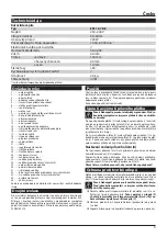
Technical Data

Hand jigsaw

Type 


EPL 12-7 BE

Voltage 


230–240 V

Power frequency  

50–60 Hz

Rated power input 

720 W

Number of strokes in idle cycle 

1 000–2 900 spm

Electronic stroke number selection 

ü

Pendulum stroke setting 

4 stages

Hoisting 


26 mm

Cut-through 

in timber 

120 mm


in colour metals 

20 mm


in steel 

10 mm

Chamfer cuts 


±45°

Quick coupling blade system* 

ü

Weight 


2.4 kg

Protection class   

II / 

*(System of tool-less circular-saw blade clamping)

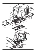
Controllers

1 ............Clamping lever 

2 ............Saw blade clamp 

3 ............Saw blade 

4 ............Additional saw blade guide 

5 ............Additional guide set screw 

6 ............Splinter guard  

7 ............Jig saw base runner 

8 ............Base runner pad 

9 ............Splinter guard locking nose  

10 ..........Chip guard 

11 ..........Extraction channel 

12 ..........Extraction adapter 

13 ..........Extraction hole 

14 ..........Extraction adapter lock 

15 ..........Extraction adapter lock retaining groove 

16 ..........Base runner set screw 

17 ..........Hexagonal (Allen) wrench 

18 ..........Base runner slope scale 

19 ..........Pendulum stroke change over switch 

20 ..........Guide bell 

21 ..........Rod 

22 ..........Stroke controller 

23 ..........Switch button 

24 ..........Switch lock button 

25 ..........Centering base runner pin 

26 ..........Centering base runner hole 

27 ..........Guide for straight cuts 

28 ..........Guide for circular cuts (circle cutter) 

29 ..........Clamping clip for the guide 

30 ..........Parallel guide stop 

31 ..........Guide locking screw 

32 ..........Hole for the circle cutter pin 

33 ..........Circle cutter pin 

34 ..........Steel base runner pad 

35 ..........Vent holes
The displayed or described accessories do not necessarily become the 

integral part of jig saw delivery.

Double insulation

To ensure maximum safety of the user, our tools are designed and built 

to satisfy applicable European standards (EN standards). Tools with 

double insulation are marked by the international symbol of a double 

square. These tools must not be grounded and a two-wire cable is suf-

ficient to supply them with power. Tools are shielded in accordance with 

EN 55014.

Scope of Use

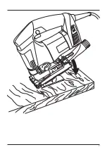
The jig saws are designed and intended for shaped and direct cutting 

of wood, plastics, steel, non-ferrous metals, aluminium and ceramics. 

They are suitable for straight and arc cuts under the angle of ±45°. Use 

the saw blades recommended by the manufacturer for the operations 

above.
The user is responsible for improper use.

Saw Blade Clamping and Removal

Attention! Risk of el. shock. Prior to start any operation, 

pull the plug out of the socket!

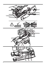
To clamp the saw blade (3), tilt the clamping lever (1) fully by one hand 

and insert the saw blade (3) by the second hand as far as the stop of the 

saw blade clamp (2). Then release the clamping lever (1) and move it to 

the initial position. (The clamping lever is equipped by a spring ensuring 

its tilting towards the jig saw body).
To remove the saw blade (3), tilt the clamping lever (1) fully by one hand 

and remove the saw blade (3) by the second hand (3) out of the saw 

blade clamp (2). If a new saw blade is not inserted, release the clamping 

lever and move it back to the initial position.

Saw blade guide setting (4)

For better guidance of the saw blade (3) the jig saw is equipped by the 

additional hard metal guide (4) mounted immediately above the work-

piece.
Using the Allen key (internal part of the scope of delivery), screw or un-

screw the additional guide set screw (5) until the guide jaws (4) nearly 

rest against the saw blade (3).
The saw blade clearance must guarantee its easy movement!

Splinter Guard

The splinted guard  (6) allows cuts with splinter-free edges even on 

the side of the cut material which the saw blade base runner (7) leans 

against (except special saw blades with inverse saw teeth).

Attention! Risk of injury in case of unwanted start of the 

tool. Prior to start any operation, pull the plug out of the 

socket!


‰

Insert the splinter guard (6) into the base runner pad (8) and push it 

as far as the saw blade. 

Attention, the locking nose (9) in the side 

groove of the splinter guard (6) must be up with respect to the 

position of the jig saw base runner (7).


‰

Set the pendulum stroke (see the chapter “Pendulum Stroke Set-

ting”) to position 1 or 2.


‰

Start the jig saw (see the chapter “Putting into Operation”).

Summary of Contents for EPL 12-7 BE

Page 1: ...P vodn n vod k pou v n P vodn n vod na pou itie Original operating manual Instrucciones de uso originales p Pierwotna instrukcja obs ugi Eredeti haszn lati tmutat EPL 12 7 BE...

Page 2: ...ury hazard Cuidado Lea las instrucciones para reducir los riesgos de que se produzcan da os Uwaga Dla zmniejszenia ryzyka urazu nale y przeczyta niniejsz instrukcj Figyelem A vesz lyek cs kkent se rde...

Page 3: ...3...

Page 4: ...taci n del material Wk adka zapobiegaj ca strz pieniu materia u Anyagkiszak t s elleni bet t 1 Ods vac adapt r Ods vac adapt r Extraction adapter Adaptador de aspiraci n Z czka adaptacyjna do odsysani...

Page 5: ...5 24 23 35 19 1 21 2 20 11 4 28 27 30 29 32 33 22 35 17 18 3 34 31 12 14 15 13 8 7 5 16 10 6 9...

Page 6: ...6 2 1 3 1 2 5 4 3 18 26 25 16 6...

Page 7: ...7...

Page 8: ...en n ad s prstem na sp na i nebo zapojov n vidlice n ad se zapnut m sp na em m e b t p inou nehod d P ed zapnut m n ad odstra te v echny se izovac n stroje nebo kl e Se izovac n stroj nebo kl kter po...

Page 9: ...d n d l c ch ez a v ez do d eva plastu oceli barevn ch kov hlin ku a keramiky Je vhodn pro rovn a obloukov ezy s hlem zkosen 45 Pro popsan operace pou vejte v robcem doporu en pilov pl tky Za neur en...

Page 10: ...pily 7 lze posunout v pod ln ose p ibli n o 5mm Z kladn poloha san listov pily 7 je takov e san jsou zcela posunu t sm rem dozadu tak e centrovac trn 25 je zatla en do centrovac ho otvoru 26 Povolte s...

Page 11: ...h a plastov ch materi lech a obec n omezuje vznik kr banc na ezan m materi lu Ocelov vlo ka san 34 je vhodn k pou it na ostatn ch materi lech Pro v m nu vlo ky san mus te nejd ve vy roubovat est roub...

Page 12: ...m p i pou it n ad Uveden hodnoty vibrac a hlu nosti se vztahuj k hlavn mu pou it elektrick ho n ad P i jin m pou it elektrick ho n ad s jin mi n stroji nebo p i nedostate n dr b se zat en vibracemi a...

Page 13: ...prstom na sp na i alebo zapojovanie vidlice n radia so zapnut m sp na om m e by pr inou neh d d Pred zapnut m n radia odstr te v etky nastavovacie n stro je alebo k e Nastavovac n stroj alebo k ktor...

Page 14: ...stu ocele farebn ch kovov hlin ka a keramiky Je vhodn pre rovn a ob l kov rezy s uhlom skosenia 45 Pre pop san oper cie pou vajte v robcom odporu en p lov pl tky Za neur en pou itie ru s m u vate Upnu...

Page 15: ...utku 16 Pozd ne posunutie san Sane listovej p ly 7 je mo n posun v pozd nej ose pribli ne o 5mm Z kladn poloha san listovej p ly 7 je tak e sane s celkom posunu t smerom dozadu tak e strediaci t 25 je...

Page 16: ...plastickej hmoty T dobre k e po dreven ch a plastov ch materi loch a v eobec ne obmedzuje vznik krabancov na rezanom materi li Oce ov vlo ka san 34 je vhodn pre pou itie na ostatn ch materi loch Pre...

Page 17: ...pri pou it n radia Uveden hodnoty vibr ci a hlu nosti sa vz ahuj k hlavn mu pou i tiu elektrick ho n radia Pri inom pou it elektrick ho n radia s in mi n strojmi alebo pri nedostato nej dr be sa za a...

Page 18: ...switch or energising power tools that have the switch on invites accidents d Remove any adjusting key or wrench before turning the power tool on A wrench or a key left attached to a rotating part of t...

Page 19: ...cutting of wood plastics steel non ferrous metals aluminium and ceramics They are suitable for straight and arc cuts under the angle of 45 Use the saw blades recommended by the manufacturer for the o...

Page 20: ...ole 26 Loosen the set screw 16 with internal hexagon on the bottom jig saw base runner side 7 using the Allen key 17 Move the jig saw base runner 7 to the requested position Then tighten the set screw...

Page 21: ...l be measured from the saw blade to the parallel guide stop 30 Tighten both locking screws 31 of the clamping clip Attention Priortomountingtheparallelguide thechipguard 10 must fixed if it shall be u...

Page 22: ...value ah vector sum for three directions and uncertainty K measured in accordance with EN 60745 Sawing wood ah D 4 5 m s 2 In accuracy of measurements K 2 0 m s 2 Sawing metal ah ID 3 0 m s 2 In accur...

Page 23: ...dedo puesto en el pulsador o el conectar la clavija con el pulsador en posici n de encendido d Antes de encender una herramienta retire todos los instru mentos de calibraci n o llaves El dejar un inst...

Page 24: ...idad con la norma EN 55014 Uso La m quina est dise ada para cortes y recortes de madera pl stico acero metales no ferrosos aluminio y cer mica Es adecuado para cortes rectos y curvos con un ngulo de i...

Page 25: ...aladora 7 e incl nela con el ngulo deseado regulan do ste seg n la escala 18 en la placa base de la sierra caladora A continuaci n apriete el tornillo regulador 16 Desplazamiento longitudinal de la pl...

Page 26: ...iete los dos tornillos de seguridad 31 de la abrazadera de fi jaci n Coloque el mandril del contorneador 33 en el agujero posterior del contorneador Zapata met lica de la placa base La placa base de l...

Page 27: ...o en la aplicaci n Los valores de emisi n indicados representan las aplicaciones principa les de la herramienta el ctrica No obstante si se emplea la herramienta el ctrica para otras aplicaciones con...

Page 28: ...28 1 2 a RCD RCD 3 a 4 a 5 a...

Page 29: ...2 7 BE 230 240 50 60 720 1 000 2 900 1 4 26 120 20 10 45 2 4 II 1 2 3 4 5 6 7 8 9 10 11 12 13 14 15 16 17 18 19 20 21 22 23 24 25 26 27 28 29 30 31 32 33 34 35 EN EN 55014 45 3 1 3 2 1 3 1 3 2 4 3 4 5...

Page 30: ...30 6 8 9 6 7 1 2 6 6 6 6 10 10 7 1 10 7 6 11 12 13 7 14 15 12 27 12 14 15 13 7 45 10 6 16 7 17 7 5 18 16 7 5 7 25 26 16 7 17 7 16 6 20 21 19 0 3 0 3 22 1 2 3 4 5 6 6 1 3...

Page 31: ...31 120 6 1 3 10 2 4 0 1 20 3 5 0 2 20 3 6 0 2 30 1 2 0 10 3 5 0 230 220 240 23 23 24 23 24 3 6 3 7 3 27 7 29 27 30 31 10 28 120 720 7 29 28 32 31 33 8 34 7 8 35 21 20 www narex cz...

Page 32: ...LpA 86 A LwA 97 A K 3 A ah K EN 60745 ah D 4 5 2 K 2 0 2 ah ID 3 0 2 K 2 0 2 EN 60745 60745 1 60745 2 11 2006 42 EC 55014 1 55014 2 61000 3 2 61000 3 3 2004 108 EC 2013 Narex s r o Chel ick ho 1932 A...

Page 33: ...palcem na wy czniku lub wtykanie wtyczki narz dzia z w czonym wy cznikiem mo e by przyczyn wypadk w d Przed za czeniem narz dzia zdj wszystkie narz dzia regula cyjne lub klucze Narz dzie regulacyjne...

Page 34: ...ia otwor w w drewnie tworzywach sztucznych stali metalach kolorowych alumi nium i ceramice Nadaje si do ci cia r wnoleg ego i ci cia ukosowego z k tem ci cia 45 Do wy ej opisanych operacji nale y u yw...

Page 35: ...e eli s zamoco wane Poluzowa rub regulacyjn 16 na dolnej stronie stopy wyrzynar ki 7 za pomoc klucza sze ciok tnego 17 Stop wyrzynarki 7 przesun zupe nie do przodu o oko o 5mm i wychyli pod wymaganym...

Page 36: ...Stalowy wk ad stopy Na stopie wyrzynarki jest zamocowany fabrycznie wk ad stopy 8 z tworzywa sztucznego Ten si dobrze lizga po drewnie i materia ach z tworzywa i og lnie ogranicza powstawanie rys na c...

Page 37: ...as u ytkowania Podane parametry emisji dotycz g wnych zastosowa elektronarz dzia Je li jednak narz dzie elektryczne zostanie u yte do innych zasto sowa z innymi narz dziami mocowanymi lub b dzie nieod...

Page 38: ...mozgat sa sor n a h l zati vezet ket h zza ki az aljzatb l az ujj t pedig vegye le a f kapcsol r l Ha az elektromos k zi szersz m mozgat sakor az ujja a f kapcsol n marad akkor a h l zathoz t rt n cs...

Page 39: ...darabolni vagy azokba ny l sokat v gni A f r sszel egyenes vagy velt vonalakat lehet f r szelni 45 k z tti d l ssz ggel A f r szel si m veletekhez csak a gy rt ltal aj nlott f r szlapokat haszn ljon...

Page 40: ...18 seg ts g vel lehet be ll tani A csavart 16 h zza meg A sz n hosszir ny elmozd t sa A f r szg p hosszanti tengely nek az ir ny ba a sz nt 7 k r lbel l 5mm es tartom nyban lehet elmozd tani A sz n 7...

Page 41: ...rt sa k zben m anyag sz nbet ttel 8 l tjuk el a g pet Ez a sz nbet t kiv l an cs szik a m anyag s fa munkadarabokon s megel zi a munkadarab fel let nek a megkarcol d s t Az ac l sz mbet t 34 haszn lat...

Page 42: ...m okozta rezg s s zajterhel sek el zetes ki r t kel s hez A felt ntetett rezg s s zajszint rt kek az elektromos k ziszersz m f felhaszn l s ra vonatkoznak M s felhaszn l s vagy egy b szersz m befog s...

Page 43: ...43...
Page 44: ...na na ich webov ch str nkach www narex cz v sekcii Servisn miesta The current list of authorized service centres can be found at our website www narex cz section Service Centres La lista actual de los...

Reviews: