


English
15
Commissioning and use
Any unauthorised use might cause damage to the tool. Therefore follow
these instructions:
- Always use sharp drill bits.
- Load the tool to avoid any significant reduction of speed or stoppage.
- Always change the speed gear when the machine is idle or at the
machine slow-down at low speed, in no case during the drilling or
when the machine is otherwise loaded.
Check whether the data on the name plate correspond with the actual
power supply voltage. Tools designed for 230 V may be connected also
to 220 / 240 V.
Additional handle
For safety reasons always use the additional handle (11), firmly mounted on
the clamping neck (3). The stop bar (12) can be used to adjust the drilling
depth. By rotating the handle the position of the addition al handle and the
depth stop can be modified.
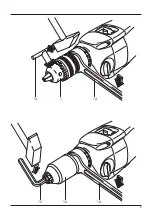
Clamping of drill bits
Chuck with ring gear
Open the chuck to allow mounting of the tool. Mount the tool on. Mount
the tool on and, using the chuck hook (13) clamp in evenly.
Quick-tightening chuck
Open the chuck to allow mounting of the tool. Mount the tool on.
Tighten the quick-tightening chuck by your hand so strongly that a “click”
sound is heard clearly. Thus the chuck will be secured automatically.
This lock will release again if you turn the sleeve contra directionally to
remove the tool.
Be careful as the chuck gets hot:
In case of longer work tasks, especially in impact drilling, the chick
might get very hot. In this case you are recommended to wear
protective gloves.
Switching on and off
By pressing the switch button (7) the machine activates and releasing the
button stops it.
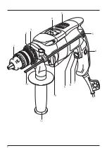
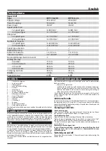
Controls
1 ............ Chuck with ring gear
2 ............ Spots on spindle
3 ............ Clamping neck
4 ............ Lever for impact shifting
5 ............ Air vents
6 ............ Latching pin
7 ............ Switch / controller
8 ............ Speed pre-selection wheel
9 ............ Alteration switch lever
10 .......... Gear-shifting lever
11 .......... Additional handle
12 .......... Stop bar
13 .......... Chuck hook
14 .......... Spanner
15 .......... Socket screw wrench
16 .......... Quick-tightening chuck
The displayed or described accessories need not be included in the delivery
package.
Double insulation
To ensure maximum safety of the user, our tools are designed and built to
satisfy applicable European standards (EN standards). Tools with double
insulation are marked by the international symbol of a double square.
These tools must not be grounded and a two-wire cable is sufficient to
supply them with power. Tools are shielded in accordance with EN 50114.
Use
The machine is intended drilling in wood, metal, ceramic and plastic.
Machines with electronic control and right/left rotation are also suitable
for screwing and thread cutting ( Only for soft screwdriving applications).
In addition, the machine is designed for impact drilling in brick, concrete
and stone as well as for drilling in wood, metal, ceramics and plastics.
Machines with electronic control and right/left rotation are also suitable for
screwing and thread-cutting.
The user alone is responsible for any liabilities caused by usage other than
intended.
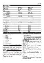
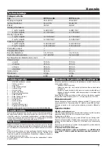
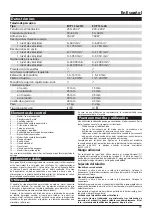
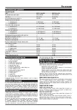
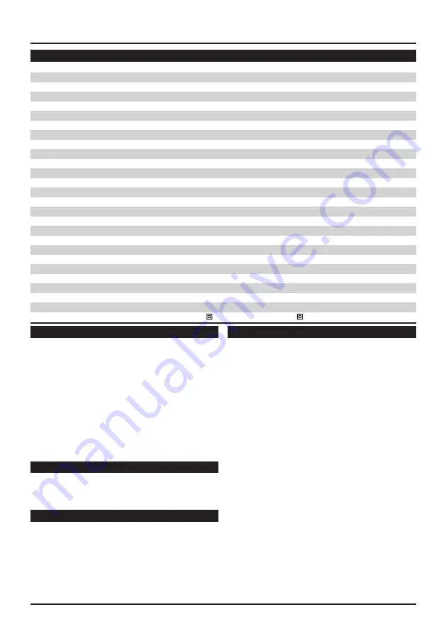
Technical data
Impact drill
Type
EVP 13 G-2H3
EVP 13 G-2A
Supply voltage
230–240 V
230–240 V
Power frequency
50–60 Hz
50–60 Hz
Power input
760 W
760 W
Speed under load
1st speed gear
0–600 min
-1
0–600 min
-1
2nd speed gear
0–1 750 min
-1
0–1 750 min
-1
Idle speed
1st speed gear
0–1 100 min
-1
0–1 100 min
-1
2nd speed gear
0–3 050 min
-1
0–3 050 min
-1
Number of impacts
1st speed gear
0–22 000 min
-1
0–22 000 min
-1
2nd speed gear
0–61 000 min
-1
0–61 000 min
-1
Speed pre-selection
ü
ü
Right-left turning
ü
ü
Extent of chuck dia.
1.5–13 mm
1.5–13 mm
Thread on spindle
1/2“-20 UNF
1/2“-20 UNF
Quick-tightening chuck Auto-Lock
û
ü
Drilling dia. max
into steel
13 mm
13 mm
into aluminium
25 mm
25 mm
into wood
45 mm
45 mm
into concrete
20 mm
20 mm
Clamping neck dia.
43 mm
43 mm
Weight
2.1 kg 2.2 kg
Protection class
II /
II /
Summary of Contents for EVP 13 G-2A
Page 3: ...3...
Page 4: ...4 1 2 3 4 5 5 6 7 8 9 10 11 12...
Page 5: ...5 1 13 14 15 16 14...
Page 22: ...o 22 1 2 a RCD RCD 3 a 4 a 5 a a...
Page 34: ...34...
Page 35: ...35...


