C2006 HYDRAULIC SHEAR INSTRUCTIONS BOOK 28
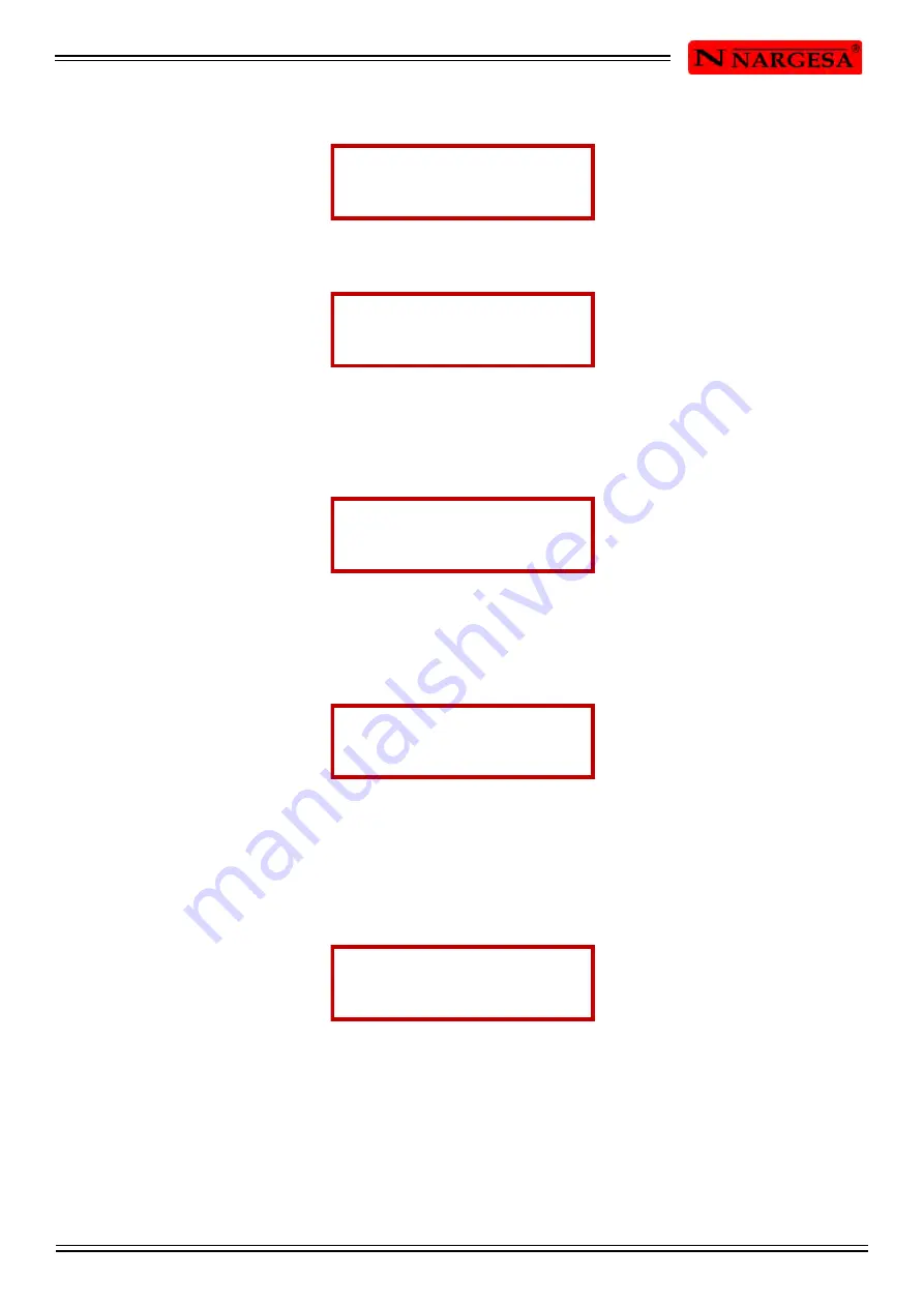
Then insert the second number (4), followed by the third one (3), these are shown on screen:
Picture 52. Inserting a new figure
Picture 53. Inserting a new figure
After press the key according to the Decimal point and it will be seen on screen what comes below:
Picture 54. Inserting a new figure
Finally insert the last number (2, in this case), you will get a new figure, as it can be seen in Picture 55:
Picture 55. Inserting a new figure
Once these simple steps are made, press the Return key to continue in order to confirm the inserted
value.You could see on the display the information shown in the picture below, whenever the new inserted
figure is not higher than the top length:
Picture 56. Detail of block 2 with the new figure in cell nº 9
Any time you want to cancel the operation while you are inserting a new figure, just press the ESC key.
Then you will see the block again on the screen , as well as the cell you were before deciding to insert a
new figure.
BLOCK 02 0000 AU
........................ 54 mm
BLOCK 02 0000 AU
........................ 443 mm
BLOCK 02 0000 AU
........................ 443 mm
BLOCK 02 0000 AU
........................ 443 mm
BLOCK 02 0000 AU
CELL 9 = 443.2 mm
Summary of Contents for C2006
Page 2: ...Thank you for choosing our machines www nargesa com...
Page 39: ...C2006 HYDRAULIC SHEAR INSTRUCTIONS BOOK A 2 A1 List of parts...
Page 40: ...C2006 HYDRAULIC SHEAR INSTRUCTIONS BOOK A 3...
Page 41: ...C2006 HYDRAULIC SHEAR INSTRUCTIONS BOOK A 4...
Page 42: ...C2006 HYDRAULIC SHEAR INSTRUCTIONS BOOK A 5...
Page 43: ...C2006 HYDRAULIC SHEAR INSTRUCTIONS BOOK A 6...
Page 44: ...C2006 HYDRAULIC SHEAR INSTRUCTIONS BOOK A 7...
Page 45: ...C2006 HYDRAULIC SHEAR INSTRUCTIONS BOOK A 8...
Page 46: ...C2006 HYDRAULIC SHEAR INSTRUCTIONS BOOK A 9...
Page 47: ...C2006 HYDRAULIC SHEAR INSTRUCTIONS BOOK A 10 A2 Detail of treaders...
Page 48: ...C2006 HYDRAULIC SHEAR INSTRUCTIONS BOOK A 11...
Page 49: ...C2006 HYDRAULIC SHEAR INSTRUCTIONS BOOK A 12 A3 Detail of guided gauge...
Page 50: ...C2006 HYDRAULIC SHEAR INSTRUCTIONS BOOK A 13...
Page 51: ...C2006 HYDRAULIC SHEAR INSTRUCTIONS BOOK A 14...
Page 52: ...C2006 HYDRAULIC SHEAR INSTRUCTIONS BOOK A 15 A4 Detail of dirving gauge...
Page 53: ...C2006 HYDRAULIC SHEAR INSTRUCTIONS BOOK A 16...
Page 54: ...C2006 HYDRAULIC SHEAR INSTRUCTIONS BOOK A 17...
Page 55: ...C2006 HYDRAULIC SHEAR INSTRUCTIONS BOOK A 18 A5 Detail of Hydraulic kit...
Page 56: ...C2006 HYDRAULIC SHEAR INSTRUCTIONS BOOK A 19...
Page 57: ...C2006 HYDRAULIC SHEAR INSTRUCTIONS BOOK A 20...
Page 58: ...C2006 HYDRAULIC SHEAR INSTRUCTIONS BOOK A 21 A6 Detail of activation triangular connecting rod...
Page 59: ...C2006 HYDRAULIC SHEAR INSTRUCTIONS BOOK A 22...
Page 60: ...C2006 HYDRAULIC SHEAR INSTRUCTIONS BOOK A 23 A7 Detail of triangular rod...
Page 61: ...C2006 HYDRAULIC SHEAR INSTRUCTIONS BOOK A 24...
Page 62: ...C2006 HYDRAULIC SHEAR INSTRUCTIONS BOOK A 25 A8 Detail of cylinder...
Page 63: ...C2006 HYDRAULIC SHEAR INSTRUCTIONS BOOK A 26...
Page 64: ...C2006 HYDRAULIC SHEAR INSTRUCTIONS BOOK A 27 A9 Electric maps...
Page 65: ...C2006 HYDRAULIC SHEAR INSTRUCTIONS BOOK A 28...
Page 66: ...C2006 HYDRAULIC SHEAR INSTRUCTIONS BOOK A 29...
Page 67: ...C2006 HYDRAULIC SHEAR INSTRUCTIONS BOOK A 30...
Page 68: ...C2006 HYDRAULIC SHEAR INSTRUCTIONS BOOK A 31...
Page 69: ...C2006 HYDRAULIC SHEAR INSTRUCTIONS BOOK A 32...
Page 70: ...C2006 HYDRAULIC SHEAR INSTRUCTIONS BOOK A 33 A10 Hydraulic map...


