background image

MC150B BENDING MACHINE INSTRUCTION BOOK                                                                                                                                    16 


7. ASSEMBLING OF THE ROLLERS


IMPORTANT NOTE: 

The clamping nut of the rollers should never be tightened with a wrench and only by hand. If pipe rollers 
are being used, the nuts must be loose.


1. Front nut 

M30x200 


2. Thick washer


3. 55mm Upper roller 


4. 40mm Upper roller


5. 25mm Upper roller


6. 55mm Lower rollers


7. 40mm Lower rollers


8. 25mm Lower rollers


Figure 12. Nomenclature of the rollers and assembly 

Summary of Contents for MC150B

Page 1: ...INSTRUCTIONS BOOK PRADA NARGESA S L Ctra de Garrig s a Sant Miquel s n 17476 Palau de Santa Eul lia Girona SPAIN Tel 34 972568085 nargesa nargesa com www nargesa com SECTION BENDING MACHINE MC150B...

Page 2: ...Thank you for choosing our machines www nargesa com...

Page 3: ...maintenance 4 INSTALATION AND START UP 4 1 Positioning the machine 4 2 Dimensions and work area 4 3 External admissible conditions 4 4 Instructions for connecting to the power supply 5 INSTRUCTIONS F...

Page 4: ...s and sizes Apart from the standard rollers the manufacturer also offers different types of additional rollers to produce other types of bending according to the configuration of the material to be ha...

Page 5: ...ontal Upper roller adjustment spindle Roller guides deformation adjustment Top roller smooth Lower rollers knurling Box door General switch Comand Upper housing Bending rollers Upper roller adjustment...

Page 6: ...acteristics Motor power 0 75 Kw 1 CV a 1400 r p m Voltage 3 phased 230 400 V or 1 phased 230 V Intensity 3 5 2 A Type of pull Two rollers Roller speed 6 r p m Roll diameter 127 mm Axes useful length 7...

Page 7: ...f the machine are located under the main upper cover that protects the mechanisms Although the major mobile elements are protected by the upper cover it is necessary to take special precautions during...

Page 8: ...of the machine from the anchor point designed for this purpose defined in figure 4 using a crane or forklift Figure 4 Transportation of the machine The design of the section bending machine MC150B all...

Page 9: ...shouldn t be stored in a place that does not meet the following requirements Humidity between 30 and 95 Temperature of 25 C to 55 C or 75 C for periods not exceeding 24hrs remember that these temperat...

Page 10: ...ith the help of a rag or a spatula Spread the grease evenly without creating excesses or clumps Once the machine is lubricated using the upper roller adjustment handle that controls the height of the...

Page 11: ...nd work area The dimensions must be considered when the machine is being placed the working area for the operator and the possible lengths of the parts to be worked The bending machine can be used by...

Page 12: ...ine guard contactor Change connection of motor bobbins To connect the machine to a three phased 400V drive motor bobbins must be star like connected default On the other hand to connect the machine to...

Page 13: ...wdriver Figure 8 Change transformer primary connection Adjusting Intensity of engine keeper Depending on the line voltage the current consumption varies the of the machine It is therefore necessary to...

Page 14: ...material input Use the millimetre scale to recognize the position The distance between the deformation adjustment roller guide and the work surface must be modified in order to adjust the alignment o...

Page 15: ...Take the rear support off and fix with the screw and washer located on the top of the MC150B Afterward ensure the machine with a locking device This device will link the crane cable with safety ring...

Page 16: ...in the extremities between the rollers and the part Users of the machine are recommended to handle the part to be bent firmly with one hand and to move the hand according to the progress of the bendin...

Page 17: ...hould never be tightened with a wrench and only by hand If pipe rollers are being used the nuts must be loose 1 Front nut M30x200 2 Thick washer 3 55mm Upper roller 4 40mm Upper roller 5 25mm Upper ro...

Page 18: ...x 45 25 x 25 300 200 40 x 40 x 3 350 50 x 50 x 3 700 50 x 50 x 3 600 50 x 50 x 3 450 70 x 70 x 4 40 x 40 x 3 750 350 40 200 40 200 40 150 40 200 80 70 40 500 400 150 40 250 40 250 40 200 40 250 80 60...

Page 19: ...ckness 1 GAS 33 250 mm 1 WHITWORT 25 401mm When pipe sizes are small two sizes are included in the same roller Eg 20 35 or 1 2 1 1 4 It is advisable to clean up very well the rollers before using stai...

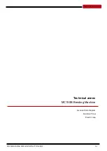
Page 20: ...MC150B BENDING MACHINE INSTRUCTION BOOK A 1 Technical annex MC150B Bending Machine General Parts Diagram Electrical Panel Electric map...

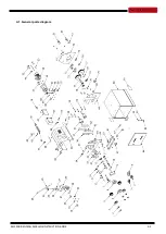
Page 21: ...MC150B BENDING MACHINE INSTRUCTION BOOK A 2 A1 General parts diagram...

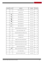
Page 22: ...MC150B BENDING MACHINE INSTRUCTION BOOK A 3...

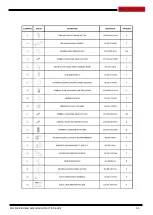
Page 23: ...MC150B BENDING MACHINE INSTRUCTION BOOK A 4...

Page 24: ...MC150B BENDING MACHINE INSTRUCTION BOOK A 5...

Page 25: ...MC150B BENDING MACHINE INSTRUCTION BOOK A 6...

Page 26: ...MC150B BENDING MACHINE INSTRUCTION BOOK A 7...

Page 27: ...MC150B BENDING MACHINE INSTRUCTION BOOK A 8 A2 Electrical Panel Double switch Transformer Breaker Switch...

Page 28: ...MC150B BENDING MACHINE INSTRUCTION BOOK A 9 A3 Electric map...

Page 29: ...y has been extended up to three years WARRANTY REGISTRATION 1 Among www nargesa com on our site 2 Select the menu Warranty Registration 3 Complete the form with your details and press 4 Message Sent c...

Reviews: