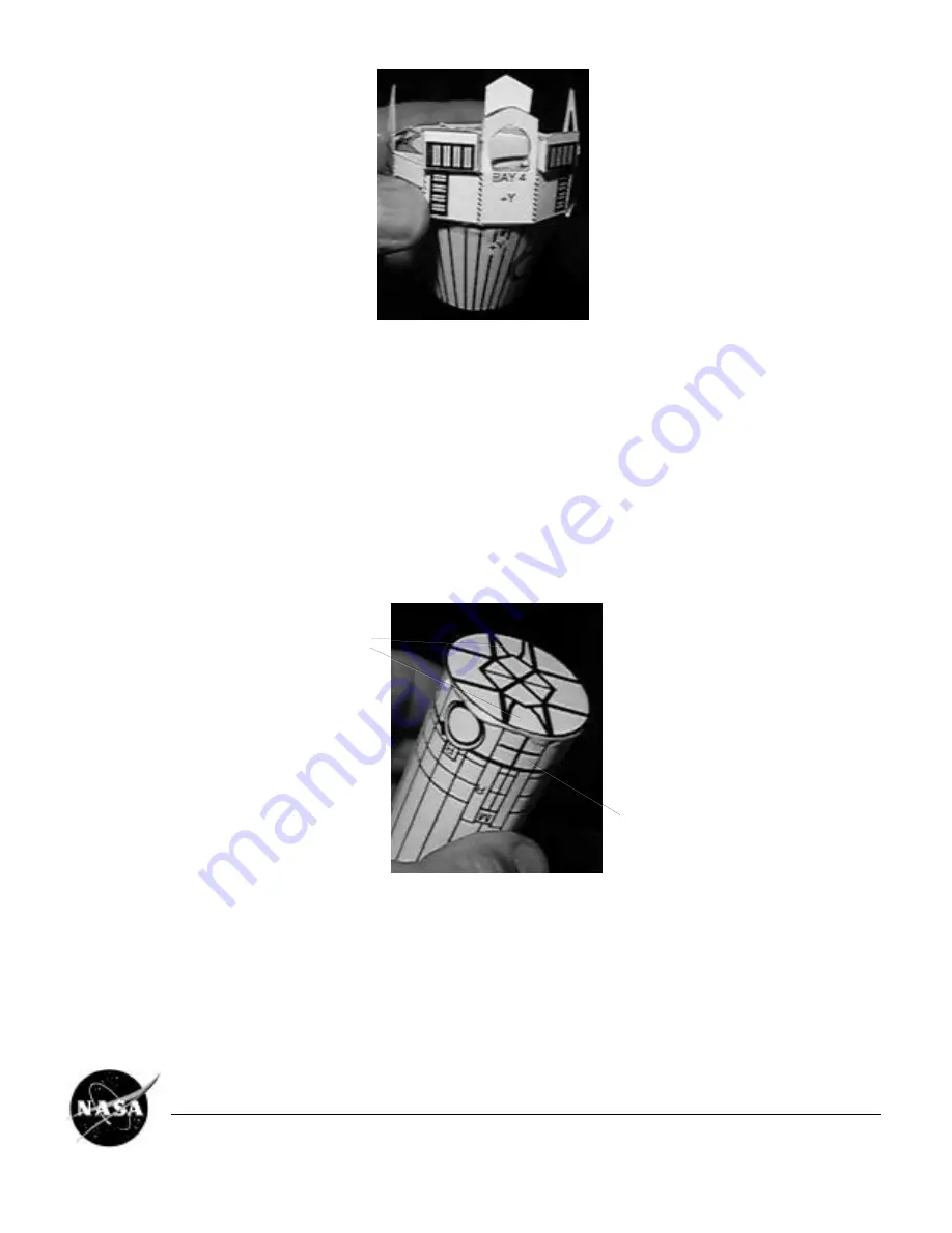
• 2. ASSEMBLE THE PROPULSION MODULE
❐
Cut out the rectangular PROPULSION MODULE AND LOWER EQUIPMENT MODULE STRUCTURE from Parts Sheet
2. This model part will be referred to as the PM.
❐
Smear some glue along the end of this piece marked GLUE, and roll it around into a cylinder. Overlap the opposite end
onto the glue, press together, and let the glue dry. It might be helpful to hold a popsicle stick inside the cylinder to help
press the seam together.
❐
Adjust the shape of the piece into an even cylinder.
❐
Cut out the circular ENGINE GIMBAL ASSEMBLY (EGA) from Parts Sheet 2. This part is greatly simplified; on the
spacecraft, it is an arrangement of trusses, actuators, etc. which support the main engines, and allow them to be
swiveled back and forth.
❐
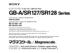
Glue the EGA onto the lower end of the PM. That's the end marked with an arrow laZ. Align the EGA with its
printed detail facing out, rotated so that its "M" shaped features line up with the two large + features on the PM (there's
a third large + which will not line up).
M-Shaped Features
Large + Feature
❐
Cut out the BIPROPELLANT TANK HALVES from Parts Sheet 2. Fit them together at right angles, slot into slot, and
secure with glue. These intersecting pieces represent two domed cylindrical tanks.
❐
Before installing the BIPROPELLANT TANKS, some trimming needs to be done. Set the SPACECRAFT BUS's
attached UPPER EQUIPMENT MODULE (narrow end) down into the top of the PROPULSION MODULE. Stand the
PROPULSION MODULE right-side up on your work surface. Align the two pieces so the BUS is perfectly level, in
alignment with the PM.
Cassini Spacecraft 1/37 Scale Model
EB-1999-04-001-JPL
Page 5


