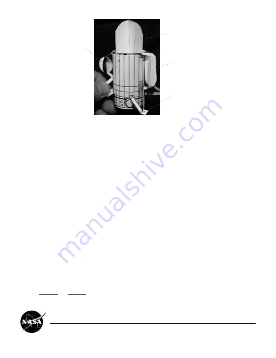
center them in between.)
Helium Tank
Bipropellant Tank
Monopropellant
Tank
RCS Thruster Cluster
❐
Cut out the PRESSURANT CONTROL PANEL from Parts Sheet 2, and smear some glue down the center of the non-
printed side, in the long dimension.
❐
Set the panel onto the PM, its center covering the words PRESS PANEL. Align its top with the T on the PM. Its larger
rectangle is on top. Leave the panel flat to stand out from the PM; don't bend it on.
❐
Cut out the PROPULSION CONTROL PANEL from Parts Sheet 2, and attach it to the PM in the same manner,
centering it on the words PROP PANEL, and aligning the top of its larger rectangle at the short line above the wording.
Monopropellant (hydrazine) supplies the RCS thrusters. Bipropellants (hydrazine from one bipropellant tank, nitrogen
tetroxide from the other), which ignite when mixed, feed the main engine(s). Helium is used to pressurize the
propellant tanks. The small circle on the PROPULSION CONTROL PANEL represents a small helium tank to be used as
a "one-shot" helium recharge for the Monopropellant tank.
❐
Now is the time to make a stand for your model. Using the tracing of the UPPER EQUIPMENT MODULE made in
section 1, cut out a sheet of clear plastic (such as an overhead transparency) in its shape. Roll its ends together and
overlap them a bit, and secure neatly with clear tape. Alternatively, a small clear plastic beverage cup might be used: cut
a circular hole centered in the bottom, 2.5 cm or one inch, in diameter.
❐
Cut out the MAIN AND BACKUP ENGINES halves from Parts Sheet 2. Fold over the rectangle marked GLUE 90° with
printed side out.
❐
Fit the two small pieces together with the single larger piece at right angles, slot into slot, and secure with glue. These
intersecting pieces represent two bell-shaped engine nozzles.
❐
Apply glue to the rectangle marked GLUE, and set the piece down onto the ENGINE GIMBAL ASSEMBLY at the
bottom of the PM. Center it, and align it lengthwise touching the two M-shaped printed features.
❐
Glue your clear plastic model stand to the EGA at the bottom of the PM. The MAIN AND BACKUP ENGINES must be
inserted into the small opening of the stand, and the larger opening will rest on the table. Center the stand with the
model. Adjust your stand so it holds the PM nicely vertical, and rests squarely on a table surface.
3. INSTALL THE HUYGENS PROBE ADAPTER
❐
Cut out the PROBE SUPPORT RING BASE from Parts Sheet 5. Apply low-moisture glue (such as a glue stick) to the
area marked GLUE, and roll the opposite end around to overlap it. Adjust to make an even, round ring (with arms
attached).
❐
Cut out the PROBE SUPPORT RING from Parts Sheet 5, and place it flat on your work surface. Set the PROBE
SUPPORT RING BASE down on top of it, with its round vertical ring contacting the flat ring near its outer edge. Join the
rings at one point with one drop of glue.
Cassini Spacecraft 1/37 Scale Model
EB-1999-04-001-JPL
Page 7


