background image

Summary of Contents for Saturn S-1 Stage

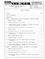
Page 1: ... J HANDLING TRANSPORTING AND ERECTION INSTRUCTIONS SATURN S l STAGE SA 1 GEORGE C MARSHALL SPACE FLIGHT CENTER HTTP HEROICRELICS ORG HUNTSVILLE ALABAMA ...

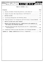
Page 2: ... Boost er from Transport er and Positioning on Tower Thrust Ring 0 a 0 0 0 0 0 0 0 0 0 a 0 U 0 0 0 0 a 0 0 0 0 J C 0 0 0 0 0 v 0 0 0 0 0 G OO 0 a 0 0 0 0 0 0 0 I 0 0 0 28 30 REMOVING BOOSTER FROM TEST TOWER Ovooooouooooooooooooooo o ooooooooooouo 35 301 Preparing Boost er f or Rem oval ooooovooo oooo o ooo ooooo ooooooooooooo ooo 35 302 Removing Boost er from Tower Thrust Ring and Positioning on T...

Page 3: ... 64 2 0 2 Removing Boost er from Transport er and Positioning on Launch Pedestal 0 72 30 REMOVING BOOSTER FROM LAUNCH PEDESTAL 00000000000000000000000 00000000 0 79 40 REMOVI NG RING SECTIONS WITH FIN I IDENTIFICATION AND PRESERVI NG ALL RING DETAILS AND ATTACHING HARDWARE 0000000 00 0000000 000000 0 000000000 80 4 1 Removing Forwar d and Rear Ring Sect i ons w ith Fin I Ident ification front Tran...

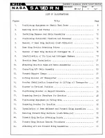
Page 4: ...ssemblies 0 0000 000 00 00 0 0 0 23 11 Connect ing Aft Cable Assembly 00 o 0 0000 00 00 0 000 0 25 12 Forward Support Clamps o 00 00 0 0000 000 0 0 00 000 0 0 27 13 0 Lifting Boost er off Transport er 0 0 000 0 00 0 0000 000 29 14 Boost er Stabilizat ion Preparat ory t o Lift ing off Transporter 0 31 15 Boost er in Vert ical Posit ion 0000000 0 0 0 0 0 0 0 0 33 160 Positioning Boost er on Support ...

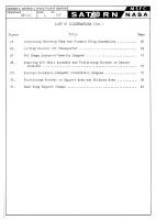
Page 5: ...r off Transpor er 0 0 0 0 0 00 69 27 8 1 St age Cen t er or Gravity D i agram 0 0 0 71 28 Removing Af t Cable Assembly and Posit ioning Booster on Launch Pedest al 0 III 0 000 0 0 Q 0 0 0 e 0 II 0 0 0 0 0 0 0 0 00 75 29 Boost er to Launch Pedestal Orient ation Diagram 77 30 Posit ioning Boost er on Support Arms and Holddown Arms 0 78 31 0 Rear Ri ng Support Clamps Q 0 0 0 0 0 u 0 0 III 0 0 0 oJ II...

Page 6: ...er stat i c t est firing Chapt er II consi st s of st ep by st ep procedures for removi ng t he forward and rear ring sections posi t i oning and erecting the Boost er from t he launch pedest al and preservat i on of t ooli ng for shi ppi ng A complet e manual containing general inst ructions for t he Sat urn S I Transport er and i ncluding a separat e Tabl e of Cont ent s List of Illust rations a...

Page 7: ...PROCEDURE PAGE OF ...

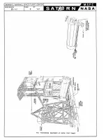
Page 8: ... form and personnel to a height necessary for attachi ng bumper assembly D 10426438 t wo bumpers D 10426434 and cable assemblies J 10424771 See figure 2 1 2 1 1 Remove doors D 10411708 and pl at es D 10411753 a ttached t o int erst age fairing and second st age adapt er o gain access t o bumper and forward sling assembly attaching point s At ta ching point s are at I beams No 3 4 5 6 and 7 1 2 1 2...

Page 9: ...PROCEDURE EP 141 PAGE OF 8 147 FIG I POSITIONING EQUIPMENT AT STATIC TEST TOWER ...

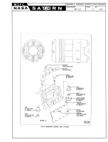
Page 10: ...REW 7513 1032 12A i r PLATE S 0 10411753 I I I Q 1I723 I REQ O l1i 1 1 I I f OE4J 621l I I I r J 1022 C8 I I REQ O LOCK PLATE C 10411724 1 Il REQ O I SCREW AN501AC416 8 I REQ O OOOR 0 10411708 SCREW 7513 1032 12A 10 REQ 0 0 DETAIL A FIG 2 REMOVING DOORS AND PLATES REF OWG 10411701 ...

Page 11: ...EW BOLTS WASHER AND NUTS SHALL BY INSTALLED USED HARDWARE TO BE DISCARDED NOTE WIPE OFF ALL LUBRICANT FROM BOOSTER PARTS WITH CLEAN RAGS AT TIME OF REMOVAL OF SLING ASSEMBLIES TOROUE HEAD OF BOLT NAS 156 68 TO 6000 INC LBS 500FT LBS LUBRICATE THREADS SHANK OF BOLT AND EACH SIDE OF WASHERS BEFORE INSTALLATION WITH MOLYKOTE TYPE G 2 CABLE ASSY J 1042477il R 2 BOLT NAS156 68 REF f i 2 WASHER NASI43 1...

Page 12: ... forward of the rear r ing so t hat the plat f orm i s resting firmly in proper posit ion for removal of t he r ear r i ng section w ith Fin III identifica tiono See f i gure 4 W orking f rom t he hori zontal pla tform complete t he followi ng procedures g 103 0201 Connect r i ng handling bracket s t o rear ring sect ion with Fin III ident i f icat ion w ith nuts and bolt s 0 See f i gure 59 detai...

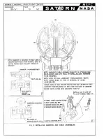
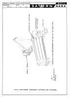
Page 13: ...TER PROCEDURE EP 141 PAGE OF 12 147 w z 0 U W l Ql o E E 0 o LL I l 0 l I l LL J 0 o LL Z 0 0 w 0 W I l LL o z Q I U W o 0 o Ql o o z 0 W 0 0 J Z o E w 0 I 0 0 o I U W Z W og 00 I Ill FIG 4 POSITIONING HORIZONTAL PLATFORM AND PERSONNEL ...

Page 14: ...E EP 1 41 AFT VIEW LOOKING FORWARD I REAR RING IJ AF 12004 2 01 ASSEMBLY RING HANDLING BRACKET IJ I04244401 TYPICAL F OR ALL RING SECTIONS FIG 5 REMOVAL OF REAR RING SECTIONS FLIGHT CENTER OF 13 147 CHOKER LINE TRANSPORTER ...

Page 15: ...CE FLIGHT CENTER PROCEDURE EP 141 PAGE OF 14 147 SCREW J AF 12004 2 17 ROTATED 180 DETAIL A C6 ECTING B AF 12004 2 3 TEE BRACKET D AF 12004 2 2 TYPICAL AT OUTRIGGERS NO 2 4 6 AND 8 FIG 6 RE AR RING SECTION ATTACHING POINTS ...

Page 16: ... Conne d tag line to r ear ri ng section w ith Fin III ident i f ication and hoi st off of boost er and lower i nt o working area o Use tag line t o control swinging move ment 0 See f i gure 50 10 3 3 5 Disconnect r ing handling brackets from rear ring sec t ion wit h Fin III i dent i f ication and remove choker lines from mobile crane hooks 10303 06 Using mobile crane lower horizontal pl at form ...

Page 17: ... posit ioned t o maintain a taut tag line lift rear ring sect ion wit h Fin IV identification free of t he bOOster and lower int o working area wit h mobile crane See figure 5 1 3 4 9 Disconnect ring handling brackets from rear ring sec tion and remove choker lines from mobile crane hooks 103 4 10 Usi ng fork lift rai se t ransportation ring plat form and personnel t o a height as necessary and di...

Page 18: ...o 1 305 8 Lower personnel and t ransportat ion ring plat form wit h fork lif t and clear immediat e area preparat ory t o hoist i ng rear ring sect i on free of boost er o 1030509 Wit h personnel posi tioned t o maintain a t aut t ag l i ne lift rear r ing sect i on w ith Fin II i dentificat ion free of boost er and lower i nt o worki ng area wit h mobile crane 0 See figur e 50 1 3 501 0 Disconnec...

Page 19: ...ROCEDURE EP 141 PAGE OF 18 147 TEE BRACKET D AF 12004 2 2 SCREW J AF 12004 2 8 NOTE OUTRIGGER 8 CONNECTING PIN OMITTED FOR CLARITY WASHER J AF 12004 2 7 SET SCREW Jl lrl1 J AF 12004 2 10l FIG 7 REMOVAL OF REAR RING SECTION AT OUTRIGGER NO 2 ...

Page 20: ... a CD b w b z z a a w a w I 0 10 b b z z a w 0 a a t I a 0 0 LL Z S lI H 0 LL 0 J W l LL t z 0 z 0 i a b f b 0 z b z 0 a Z a en w w z a I W a I a a l I a l LL I I 0 0 0 FIG 8 I DENTIFICATION OF FIN LINE AND OUTRiGGER NUMBERS ...

Page 21: ...r o 20102 Using t ower crane lower 100 t on sister block and sist er hook t o t he l oad plat form and connect the erection beam J 10427055 to t he 100 ton sist er block and sist er hook wit h pin C 1 0423816 st op C 1 0423817 and screw MS35301 111 0 See figure 9 detail Bo 20103 Place deflect or pit bridging over deflect or pit using gant ry crane o 20104 Using t owing t ract or posit ion t he t r...

Page 22: ...IN CONNECTING PIN FORWARD ERECTING J CABLE ASSEMBLY J 10424 771 TYPICAL TWO PLACES 2 BUMPER 0 10426434 424657 PIN C 10424412 i 424 A_ _ 1 I I L I ____ _ _____________ _ __________ J __ NOTE 8 BUMPER ASSEMBLY 10426438 IS NOT DESIGNED TO RESIST EXCESSIVE LOADS TOWER CRANE CABLES SHALL NEVER BE LESS THAN 90 FROM THE HORIZONTAL CENTERLINE OF THE BOOSTER SO THAT THE SISTER HOOK HAS SOME VISABLE SPACE B...

Page 23: ...and connect to erection beamo See figure 30 201 5 03 Maintaining a slight tension on the cable assemblies raise t he erection beam until the erection beam rests against bumper assemblies D 10426434 See figure 90 C A UTIONg The 100 ton si ster hook block must not contact bumper assembly D 10426438 as this creates a negative angl e between the t ower crane cables and the horizontal cent erl ine of t...

Page 24: ...TER DEFLECTOR MOBILE CRANE STEP I ATTACHING CABLE ASSEMBLIES TO ERECTION BEAM FIG 10 ATTACHING ERECTION BEAM AND CABLE ASSEMBLIES PROCEDURE EP 141 PAGE 23 OF 147 STATIC TEST TOWER FT CABLE ASSEMBLY HORIZONTAL PLATFORM TRANSPORTER DEFLECTOR PIT BRIDGING STEP 2 ATTACHING AFT CABLE ASSEMBLY TO OUTRIGGER NO 5 ...

Page 25: ... GANTRY CRANE BLOCK ASSEMBLY AFT CABLE CONNECTING PIN CONNECTING LINK DOG BONE 0 10424657 NUT OUTRIGGER y ASSEMBLY 0 10423292 COTTER PIN CONNECTING PIN FIG II CONNECTING AFT CABLE ASSEMBLY A ...

Page 26: ...acket at out r i ggers No o 2 and 8 See f igure 60 2 1 50 10 Disconnect t ee brackets from outriggers No o 2 and 8 by loosening set screws and removing connecting pins See figure 60 NOTE Boost er retains the horizontal posit ion and lower sect ion of rear ring remains attached t o t rans port er 2 1 05 11 At tach t wo tag lines t o each outrigger No o 3 and 70 NOTE Tag lines t o be 1 inch diamet e...

Page 27: ...RING ________ J AF 12004 3 0 1 TRANSPORTER FORWARD VIEW LOOKING AFT HOLDDOWN ROLLER 1V J AF 12004 4 36 HOLOOOWN BRACKET J AF 12004 4 31l Y CAP SCREW i II NC 8 REa o DETAIL A 8 J AF 12004 4 32 FIG 12 FORWARD SUPPORT CLAMPS ...

Page 28: ...orter to a hei gh t that w i ll clear t he r ear ring sectiono See figure 130 20203 Using towing tract or remove t ransporter f r om stati c test ar ea o Clean and preserve t ransporter usi ng applicable specifi cations outlined in paragraphs 10205 and 102060 20204 Wit h the booster st ill in horizont al posi t i on but free of t he t ransporter y remove pin in out rigger No o 10 At tach tag l ine...

Page 29: ...E BOOSTER SO THAT THE PIN THROUGH OUTRIGGER NO 1 IS FLOATING IN THE RECESS OF TEE BRACKET STEP I STABILIZING BOOSTER PREPARATORY TO LIFTING OFF TRANSPORTER FIG 13 LIFTING BOOSTER OFF TRANSPORTER PROCEDURE EP 14fAGE 29 OF 147 STEP 2 LIFTING BOOSTER OFF TRANSPORTER stATIC TEST TOWER ...

Page 30: ...OUTFllGCiE R 10 1 PIN CONNEC TING B AF 12004 2 3 FIG 14 BOOSTER STABILIZATION PREPARATORY TO LIFTING OFF TRANSPORTER ...

Page 31: ...PROCEDURE PAGE OF ...

Page 32: ...MBLY 1 f I NO 5 OUTRIGGER STEP I DETACHING AFT CABLE ASSEMBLY FROM OUTRIGGER NO 5 MOBILE CRANE FIG 15 BOOSTER IN VERTICAL P SITION o STEP 2 POSITIONING BOOSTER ON TEST TOWER PROCEDURE EP_1 GE 33 OF 147 OUTRIGGER SUPPORT BRACKET NUl WASHE TEST TOWER D PIN ASHE 9 TIEROD NUT A TYPICAL 8 PLACES ...

Page 33: ... and bumpers D 10426434 and t he installat ion of original hardware at I beams No 0 3 4 5 6 and 7 1s essentially t he reverse of ins i ructi ons as out lined i n paragraphs 1020101 through 1020 1040 See fi gur es 3 and 40 202 01 6 C lear t est t ower area 30 REl10VI N G BOOSTER FROM TEST TOWERo 3 0 1 Prepar i ng BO Q st er for RemovaL 30101 Pl a ce deflector pit br i dging over deflector pit using...

Page 34: ...GEORGE C MARSHALL SPACE FLIGHT CENTER PROCEDURE EP 1 41 PAGE OF 36 147 NOTE SHROUD NOT SHOWN FOR CLARITY OUTRIGGER A TYPICAL 8 PLACES FIG IS POSITIONING BOOSTER ON SUPPORT BRACKET ...

Page 35: ...be Usedo Lubricating the shanks and t hreads of bolt s NAS156 68 and each si de of t he a shers NAS143 1 6 and NAS143 16c and obtaining a t orque value of 6000 inch pounds 500 foot pounds from the head of bolts is mandat ory t o prevent shearing of t he attachment hardware during removal of boost er from t est t ower and posi t i oni ng on transpor t ero 30101 2 Q uality Cont rol Division shall in...

Page 36: ...bracket is attached t o rear ring sect i on wit h Fin III ident ificationo 3020 106 Screw J AFr 12004 2 s 302 0107 Screw J AF 12004 2 1 3 302 0108 Screw J AF 12004 2 17 302 010 9 Bar rel nut J AF 1 2004 2 6 30201010 C onnect i ng pin B AF 1 2004 2 3 3020 101 1 Washer J AF 1 2004 2 5 30201012 Bal lok pin J AF 12004 32 9 30201 0 13 Bal lok pin J AF 12004 2 24 30201 014 Bracket J AF 12004 4 31 3020 0...

Page 37: ... form and personnel t o t he ground and move mobile crane and hori zontal plat form clear of t ransporter ares o 30209 Using t ower crane and gant ry crane simultaneously lower boost er t o a horizontal position directly above t ransport er o See f i gure 13 0 30201 0 Load tee brackets f or out riggers No o 2 and 8 connecting pins smal l and large Bal lok pins f or outriggers No o 1 2 and 8 on t r...

Page 38: ... See figure 12 3 2 21 Using mobile crane raise horizontal platform and personnel as necessary to disconnect aft cable assembly 0 10423292 _from outrigger Noo 5 See figure 11 0 30 2 22 Lower horizontal platform and personnel to the ground and move mobile crane and horizontal platform clear of transporter area 3 2 23 Using gantry crane position horizontal platform and personnel in front of booster i...

Page 39: ... sect ions as fo110ws g 30308 1 Ut ilizing t he 4 1 2 inch screw J AF 12004 2 18 and locator A AF 12604 2 14 in end holes of each ring sect ion aline ring sections by tapping screw heads t o insert locators into matching holes of opposite ring section See figures 6 and 70 30308 2 Install remaining two bolt s t hrough base of tee bracket at out rigger No o 2 See figure 6 303 8 3 Inst all four 8 inc...

Page 40: ...ng mobile crane with two hooks position rear ring section with Fin IV ident ificat ion opposite Fin IV on booster Contro l swinging motion with tag line See figure 5 3 3 16 Load two tee brackets and attaching hardware on transportation ring platform NOTE Tee brackets are match marked for outriggers No 6 and 7 3 3 17 Using fork lift1 raise and position the transportation ring plat form and personne...

Page 41: ... resting firmly in proper position for installation of t he upper section of the rear ringo See figure 40 303024 Connect ring handling brackets to ring section with F in III identification with nut s and bolts and attach tag lineso NOTEg Rear ring section with Fin III identification has center tee bracket attachedo 303025 Using m obile crane wit h two hooks IDwer crane hooks to rear ring section a...

Page 42: ...ion ring platform t o the ground using fork lift o 304 Bemoving Bumper Assem bly D 1 0426 J8 T Q Jlll1P J r D 1Q4 4 41 i and Two Cabl e A ssemblie s J T 10424771JI 30401 Prior t o r emoving bumper assembly D 10426438 two bumpers D 10426434 j and t wo cable assemblies J 10424771 check t hat t he followi ng part s are availableo See figure 20 3040 101 Door 0 10411708 5 requ ired 3040102 Pl s te D 10...

Page 43: ...e figure 3 det ail Co 30406 Inst all all flight hardware t hat is called out in paragraphs 3 401c 1 t hrough 304010 90 See f i gure 20 30407 Using fork lif t9 l ower t ransport at ion ring platform and person nel to t he groundo 30408 St ore bumper assembly D 10416438 two bumpers D 10426434 t wo cable assemblies J 10414771 and at taching hardware o NOTEJ Transport er and boost er are now ready to ...

Page 44: ...GEORGE C MARSHALL SPACE FLIGHT CENTER PROCEDURE PAGE OF ...

Page 45: ...350 800 1250 2250 3200 4375 5700 7200 10101 Position bri dge crane at l60 foot levelo See figure 170 10102 Lower 60 ton bl ock from bri dge crane and attach erecting beam J 10423l94 o Raise 60 ton block and erecting beam clear of the work areao See figure 170 10103 Lower 40 ton block from bridge crane and attach aft cable assembly D 10423292 0 See figure 170 Raise 40 ton block and aft cable assemb...

Page 46: ...IDGE CRANE MUST BE SET SO THAT CRANE HOOK HEIGHT IN THE RETRACTED POSITION IS 160 FEET FROM GROUND BRIDGE CRANE 60 TON BLOCK u ERECTING BEAM J 10423194 Il 4llJ II 40 TON BLOCK f i III t II AFT CABLE ASSEMBLY D I0423292 FIG 17 PREPARING SERVICE STRUCTURE FOR ERECTION ...

Page 47: ... IS 160 FEET ABOVE THE GROUND 1I 1t ln 1ftW1tfHIr ftt 40 TON BLOCK SUPPORT ARMS 60 TON BLOCK FORWARD SLING ASSEMBLY J l042666B H _ W TOWING TRACTOR M 26 FIG IS POSITIONING EQUIPMENT AT FIRING SITE AFT CABLE ASSEMBLY 0 10423292 I4 tSATURN BOOSTER TRANSPORTER TRANSPORTATION RING PLATFOR J 1042597I ORIZONTAL PLATFORM J 10426476 FORK LIFT ...

Page 48: ...ers AN960 14l6 and nuts AN325 14 for each mounting bracket as shown in figure 20 detail Eo 103 5 Using mobile crane and two sling assemblies 10427036 raise beam weldment J I0426675 into position and attach beam weld ment to mounting brackets J I0427014 and J I0427097 with bolts AN16C 54 and nuts AN325 16 as shown in figures 19 and 20 detail Eo 103 6 Attach forward sling assemblies J I0426668 to se...

Page 49: ...ORWARD SLING ASSEMBUES AND BEAM WELDMENT MOBILE CRANE FORWARD RING UPPER SECTION MOBILE CRANE HORIZONTAL PLATFORM HORIZONTAL PLATFORM J 10426476 ON TANKS STEP 2 REMOVING FORWARD FORK LIFT REAR RING UPPER SECTION ON SHROUD SATURN BOOSTER SATURN BOOSTER TRANSPORTATION RING PLATFORM s IIJ t TRANSPORTER STEP 3 REMOVING REAR RING FORK LIFT FIG 19 PREPARING BOOSTER FOR ERECTION ...

Page 50: ...ASHER BEfORE INSTALLATION WITH MOLYKOTE TYPE G NOTE WHENEVER SLING ASSt MBLIES J I0426668 ARE AT rACHED NEW BOLTS WASHERS AND NUTS SHALL BE INSTALLED USED HARDWARE TO 8E lSCARDED INSTALL LUG IN LINE OF PULL OF CABLE SEE A A SLING ASSY J 10426668 REF BOLT NASI56 68 REF 1 1 WASHER NASI43 16C REF j WASHER NAS 143 16 REF NUT C 424316IREF Yfj tiuv __ __ ____ _____ ________ ______ __ _ ____ _ jA MOUNTIN...

Page 51: ...t tension on crane cabl es Attaoh tag line to l ower pos i t i on of ring sect ion See figure 21 detail A 1 4 204 Di soonneot tee braoket from forward ring seotion at 1 beam No 5 by removi ng four bolts nuts and washers and key retai ning sorew and key See figure 22 Leave tee bracket bolted to the I beam 10403 Using fork l if t rai se and pos i tion transportation ring plat form and personnel as n...

Page 52: ...CHOKER LINE REMOVING FIG 21 FORWARD RING SECTIONS J AF 12004 3 0 ...

Page 53: ...4 3 0 PAD D AF 12004 8 3 UT J AF 12004 8 22 PLATE NUT B AF 12004 8 12 JAFI2004 8 21 SCREW BO LOCATOR lO B AF 12004 8 24 A AF 12004 3 71 l WASHER J AF 12004iH2 SHOULDER SCREW lCKET SC tW J AF 12004 8 D AF 12004 8 2 IjI IJ 120 ROTATED 180 0 1 1 _ _ _ _ FIG 22 FORWARD RING SECTION ATTACHING POINTS ...

Page 54: ...SCREW J AF 12004 3 20 SCREW J AF 12004 3 12 SPACE FLIGHT PAGE OF 57 147 TEE BRACKET F AF 12004 3 2 WASHER J AF 12004 3 9 SCREW J J AF 12004 3 8 FIG 23 FORWARD RING SECTION REMOVAL PROCEDURES ...

Page 55: ... lower hor i zontal platform and personnel to the ground0 10409 Using fork liftj lower transportation r i ng platform and personnel to I beam N oo 70 See figure 19 step 20 1040 10 Connect ring handli ng brackets to forward r i ng section with Fi n II identificati on with nuts and bolts o See figure 21j detai l Ao 10401 1 Lower crane hooks t o work area and connect t o choker l ines o 10401 2 Conne...

Page 56: ...el t o I beams Noo 6 and 70 1040 17 Thread a r ope t hr ough t he l inc h di amet er holes in base of tee brackets Noo 6 and 70 1040 1B Disconnect t ee bracket f r om I Be ams N oo 6 and 7 by removi ng four bol ts nut plate and nut s at each t ee bracket and lower t ee brackets t o the ground0 See figure 210 10401 9 Repos i t i on f ork lift rai se t ransportation r i ng platform and personne l to...

Page 57: ...iono See figure 40 Worki ng fr om t he horizont al platform complete the f ollowi ng procedures g 1 0502 1 Connect r i ng handl ing bracket s to rear r ing section with Fin III i dentification with bolts and nut s o See figure 5j det ail Ao 1050 202 Lower C rane hooks t o work area and connect to choker l ines 0 Connect choker lines to r ing handling brack et s and put s light tens ion on crane ca...

Page 58: ...g line to rear ring section with Fin III i dentification and hoi s t off of booster and lower into worki ng area o Use tag line to control swi nging move mento See figure 50 1050305 Disconnect r i ng handling brackets from rear ring sec t i on with Fin III i dentification and remove choker l i nes from mobile crane hooks 1050306 Usi ng mobile crane lower horizontal platform and personnel to the gr...

Page 59: ...atform with fork lift and clear immediate area preparatory to hoi s t i ng rear ring section f ree of boostero 1050408 With personnel positioned t o maintai n a taut tag line lift rear r i ng section with Fin IV identification free of booster and l ower into working area with m obile crane 0 See f igure 50 10 50409 Disconnect r ing handling br acket s from rear r ing sect ion and remove choker l i...

Page 60: ...505 Disconnect rear ring section with Fin II identification by perfoTming the applicabl e procedures outlined in paragraphs 1050302 and 10503030 See figure 70 1050506 Connect tag line to lower end of rear ring section with Fin II i dentificationo See f i gure 50 1050507 I nsert two barrel nuts J AF 12004 2 6 in rear ring section with Fin I identificat ion at outrigger No 2 and secure tee bracket t...

Page 61: ... beams and have two of the four bolts through their base to the ring section still installedo Tee bracket Noo 1 is intact and will not be disconnected until erection cables are connected and slight lifting forces are obtained from the service struoture Transporter is now ready to be towed into positiono 10505014 Move ring details to adequate storage area place on cross ties or equivalent and cover...

Page 62: ... 26 HORIZONTAL PLATFORM J 10426476 joIf MOBILE CRANE TRANSPORTER STEP I ATTACHING AFT CABLE ASSEMBLY AT I BEAM NO 5 FIG 24 ATTACHING AFT AND FORWARD SUNG ASSEMBLIES PROCEDURE EP 141 PAGE65 OF 147 SERVICE STRUCTURE off BRIDGE CRANE tW1 40 TON BLOCK SUPPORT ARMS 60 TON BLvL _ ERECTING BEAM J 10423194 m b 1t l EiATURN BOOSTER HORIZONTAL PLATFORM J 10426476 STEP 2 ATTACHING FORWARD SLING ASSEMBLY TO E...

Page 63: ...assembly and contact is est abl i shed between beam weldment 3 10426675 and forward sling assemblies J I042666S 0 2010 10 Remove m obile c ra ne her izont al platferm and persennel f r em f erward end ef t ranspert ero 20101 1 Us i ng towing t ractor 9 pos ition t ranspor t er and boester as shown i n figure 269 st ep 10 See figure 27 fer pes i t ion of boest er in rel at ion t o 60 and 40 ton heo...

Page 64: ...E OF ERECTING BEAM J 10433194 FORWARD SLING 68 147 ASSEMBLY J I0426668 BEAM WELDMENT J 104266751 ERECTING BEAM J 104231941 CONNECTING PIN ___ TYPICAL TWO PLACES lyL COTT ER Ir PIN A 60 TON BLOCK HOOK FIG 25 CONNECTING ERECTING BEAM AND FORWARD SLING ASSEMBLIES ...

Page 65: ...THE PIN THROUGH OUTRIGGER NO I IS FLOATING IN THE RECESS OF TEE BRACKET SEE FIGURE 14 STEP I 0 10423292 SATURN BOOSTER STABILIZING BOOSTER PREPARATORY TO LIFTING OFF TRANSPORTER FIG 26 LIFTING BOOSTER OFF TRANSPORTER SERVICE STRUCTURE SET SCREW A SUPPORT ARMS 60 TON BLOCK ERECTING BEAM J 10423194 TOWING TRACTOR M 26 PROCEDURE EP 141 PAGE rt ll j BRIDGE CRANE STEP 2 o tt 40 TON BLOCK tll2 t AFT CAB...

Page 66: ... iO N_ z V Vv J_ N N Zit 0 _CD 0 UN 10 UJ zo Z u 1ji 681 V1S w f J 0 0 In C Z u w r u w 2 o v 0 68 ViS o CD v v 0 T r r 1 J I 7 I 1 I FIG 27 S I STAGE CENTER OF GRAVITY DIAGRAM SL IZI V1S ...

Page 67: ...ove fork lift transportation ring platformjl and tee brackets clear of areao 2 205 Remove four bolts and key retaining screw and key from base of tee bracket at I beam Noo 10 2 2 6 Remove four bolts nut plate j and nuts from I beam NOolo 20207 Remove tee bracket from f orward ring section with Fin I identi fication and move tee bracket clear of areao 2 8 Remove Bal lok pin and loosen the forward a...

Page 68: ... t er o 202015 Using towing tra ctor remove t ranspor t er f rom fir ing s ite ereso 20201 6 Us i ng fork lift rai se t ranspor t at i on r i ng platform and personne l t o a hei ght necessary for inst allation of holddown block assem bl i es o 202 017 Remove connecting pin f r om outr i gger Noo 1 and attach t ag line t o out r i gger N oo 1 if conditions warrant o 202018 Lower t ransport ation r...

Page 69: ...nboard guide plates B I0418920 using bolts MS3529S 230 and washers MS35333 32 at each end of connecting pin on outriggers Noo l 3 5 and 70 See figure 300 2 2028 Retract support arms o 2 2 29 Ascertain that holddown arms are uncockedo See figure 30 step 10 2 2030 Using bridge crane 60 ton block lower booster until outriggers with holddown block assemblies attached j are approximately one eighth inc...

Page 70: ...W N l ARMS HORIZONTAL PLATFORM O I zAG LINES r nK __ MOBILE CRANE STEP I DETACHING AFT CABLE ASSEMBLY FROM OUTRIGGER NO 5 FIG 28 REMOVING AFT CABLE ASSEMBLY AND POSITIONING BOOSTER ON LAUNCH PEDESTAL SERVICE STRUCTURt f 60 TON BLOCK r ERECTING BEAM J 10423194 SUPPORT ARMS __ HOLDDOWN ARMS STEP 2 PROCEDURE EP 141 PAGE 75 OF 147 POSITIONING BOOSTER ON LAUNCH PEDESTAL ...

Page 71: ... _ ________ 00 FIG 29 BOOSTER TO LAUNCH PEDESTAL ORIENTATION DIAGRAM ...

Page 72: ...DE BRACKET J 10435895 I 1 3 5 AND 7 I OUTRIGGERS 1 1 i 1 il GUIDE HOLDDOWN ARM 4 PLATE 10435650 I fJJ y J 10435895 Ii HOLDDOWN BLOCK ASSEMBLY INBOARD 0 10418915 STEP 2 r J I _ _ __ T Y P IC AL F UR _ LACES l __ C2 4 6 AND 8 rn OUTRIGGERS I HOLD DOWN BLOCK ASSEMBLY SUPPORT ARM 10435500 1 OUTBOARD 04IB916 TYPICAL FOUR PLACES rs J ___ _ _ __ _ _ _ _ _ _ _ ____ _ _ _ _ _ ___ _ _ _ _ _ _ _ _ ___ ___ _ ...

Page 73: ...rdware removed for installation of forward sling assemblies 3 10426668 and beam weldment J l0426675 0 See figure 20 NO Eg The booster is now erected on the launch pedestal await ing the installation of the upper stageso 30 REMOVING BOOSTER FROM LAUNCH PEDESTALo Removing the booster from the launch pedestal is essenti al ly the reverse of erecting procedures paragraph 20 Speci al care must be exerc...

Page 74: ...d bolt J AF 12004 4 33 from each clamp Remove eight screws J AF 12004 4 32 that attach two brackets J AF 12004 4 31 to cradle See figure 120 40105 Using mobile crane hoist forward ring section from transporter and lower to the ground0 4 106 Disconnect choker lines and remove ring handling brackets from forward ring section with Fin I identificationo 401 7 Connect ring handling brackets to rear rin...

Page 75: ...12004 2 0 TRANSPORTER ___ 1 CLAMP J AFA 12053 ROTATED 90 DEGREES AFT VIEW LOOKING FORWARD CLAMP SUP PORTS J AFA 12053 _ ROTATED 90 DEGREES CLAMP SUP PORTS J AFA 12053 ROTATED 90 DEGREES FIG 31 REAR RING SUPPORT CLAMPS ...

Page 76: ...s and tee bracket s with dry cleaning solvent Federal Specification P S 66lj in accordance with paragraph 30201 of Military Specification MIL P 116 and apply P 3 corrosion preventive Military Specification MIL C 16l73 to mating surfaces 0 4 202 Clean attaching hardware for forward and rear ring sections 9 suppor t clamps and t ee brackets with dry cleaning solvent Federal Specification P S 66l i n...

Page 77: ...CHAPTER III GENERAL INSTRUCTIONS FOR THE SATURN S 1 TRANSPORTER TER EP 141 147 ...

Page 78: ...GEORGE C MARSHALL SPACE FLIGHT CENTER PROCEDURE PAGE OF ...

Page 79: ...1y 0 0 0 0 0 0 0 0 0 0 0 0 0 c oo 0 0 Q 0 0 Q 0 0 0 0 0 0 0 0 0 0 0 0 0 0 0 0 0 0 0 0 0 0 0 0 Operating the Brakes o 0 0 0 0 0 0 0 0 0 0 0 0 0 0 0 0 0 0 0 0 0 0 0 0 0 0 0 0 0 0 0 0 0 0 IS 0 0 0 0 0 0 0 0 Tire Change Procedure 000 000 0 0 0 0 0 0 0 0 0 0 0 0 0 0 0 0 0 000 0 0 0 0 0 0 000 00 0000000 INSTALLATION AND REMOVAL PROCEDURES 00000 000000 0000000000 00 00 0000 00 00 Installation ooooooooooo...

Page 80: ...5 9 To Replace Cradles on Transporter 00 0 0 00 0 0 00 0 00 0 0 0 0 00 0 0 1 31 5 10 Emergency Use Dolly Repairs Tire Change Etc 131 5011 Lubrication Instructions 00 0 000 000 0 0 0 0 00 00 000 0 0 0 000 0 0 00 00 00 000 00 0 00 133 60 PREPARATION OF DOLLIES FOR SHIPMENT BY COMMERCIAL CARRIER 1 33 6 1 General 0 000 000 8 0 0 0 0 0 0 100 00 0000 00 0000 0 00 0 0 0 0 0 0 0 0 0 0 0 0 00 0 0 00 000 0 ...

Page 81: ...0 0 0 0 CI 0 0 0 0 0 0 0 0 0 t 0 0 0 GO 0 Installat ion 0 0 0 0 0 a 0 0 0 0 0 0 0 0 Q 0 0 0 0 e 0 0 G 0 eo 108 109 114 115 44 Removing and Installing Dolly to Assembly Fixture 000000000 0 0 117 45 Attaching Fixture to Dolly 000000 0 0 0000000 00 0000 0 00 0000000 0 0 1 1 9 46 Tie Down Arrangement 3 1 t o Barge 000000000 000000000000 000 0000000 121 47 Portable Jack Assembly 0000 0000 GOO l 0 0 0 0...

Page 82: ...ure Title Page 55 Assembly Fixture AF 1 2004 Breakdown 140 56 Packaging Truss Weldment s and Miscellaneous Hardware 0 0 0 000000 141 57 Packaging Aft and Forward Cradles 000000000000 0 0 000000 00000000 143 58 Packaging Ring Sect ions 0 0 0 0 0 0 0 0 0 00 0 0 0 0 0 0 0 0 145 ...

Page 83: ...t ion for operat ion of portable storage jacks used to support fixt ures and cargo if st ored on a hardstand area Paragraph 90 con tains information pertaini ng t o t he preparation for shipment of a complete doll y by either mot or freight or railroad and paragraph 7 contains instruc tions for shipping t he fixture assembly by commercial means The t ransport er is specifically designed to transpo...

Page 84: ...GEORGE C MARSHALL SPACE FLIGHT CENTER PROCEDURE PAGE OF ...

Page 85: ... Power is supplied by a power unit Model No 06AK 224RV 1658E whi ch ut ilizes a gasoline engi ne t o drive a generat or The generat or is a series shunt wound unit acting as a mot or t o st art t he gasoli ne engi ne and as a generat or when t he gasoline engine i s operating Power t o star t t he gasoli ne engine is obtained from t wo 12 volt st orage batteries connect ed in series The power unit...

Page 86: ...GEORGE C MARSHALL SPACE FLIGHT CENTER PROCEDURE PAGE OF EP 141 92 147 SATURN BOOSTER JL_ r ASSEMBLY FIXTURE FIG 32 SATURN TRANSPORTER ...

Page 87: ... I o r c v lj W 20 11 dJ If A x in I r W 1 i l Cl I a I I 1 1 1 0 11_ 0 0 0 z 0 1 0 r 0 I 1 0 V frl 0 a 0 r I k n 1 0 f1 _ z I 0 CD w 10 C I 0 t 01 0 a ti l fb w Qu It 1 I If I 0 1 1 i co 1 I bJ J oB r q 01 1 00 W I d __ 0 I FIG 33 SATURN TRANSPORTER DIMENSIONS SHEET I OF 2 ...

Page 88: ... II J IV 333 50 R AR SEI T EO D SIDE l I I t I L lj n l r _ ______ J I I L J Ll I z W11 l I f __L ____ _ _ _ __ I 1 9 00 G ROmm C LEARt C 1 lB6 00 204 OO j J 216 00 AFT VIE 1 LOOKING FORWJ JID FRONT SEAT CURB SIDE FIG 33 SATURN TRANSPORTER DEMENSIONS SHEET 2 OF 2 ...

Page 89: ... OPERATOR S 01 CONTROL ASSEMBLY t BATTERY BOX 0 l Z en J 0 0 t m 0 fI G tl 0 0 m 0 0 0 n 0 r AIR FILTER m G 0 c m 0 0 m t J 1j I 0 C I t I r r RIGHT HAND WALKING BEAM G m m D T1 V l r l T 1 I t J m Z I m 0 ...

Page 90: ...GEORGE C MARSHALL SPACE FLIGHT CENTER PROCEDURE EP 141 PAGE OF 96 147 FIG 35 DRAWBAR EXTENSION ...

Page 91: ...PUMP MOTOR M r r _ _ _ _ _ _ _ _ _ _ _ _ _ _ _ _ _ l I r j 11 I J rrr q Q _ Q S l t I I I f Ii L J 2 IQtJCI I Lrrn Q i I DR I L FUSE D l V OCKED uNLd cKE l L i LOCKED UNLOCKED L J i L VL EST l _ J J POWER ON U __ QJ I l tJ V ON G E J J GENERATOR L I El RJ Off D IL ___________ _D_r Jr ll L _ _ _ _ _ _ _ _ _ _ _ _ _ _ _ _ _ _ _ _ _ _ __ _ _ _ _ _ _ _ _ _ _ FIG 36 DOLLY ELECTRICAL SYSTEM ELECTRICAL C...

Page 92: ... 3 1 r y ______ _____ ____ ______ _ __ ___ _ _f r i _ I I I I i I I I I I I I I I J A 1 A 0 L tf U 1 PUMP NO 3 uA o L r tJ PUMP NO CYLIHDER HO 1 4 t_ _ 1 J 2 i TOW l J F l lUi r C STEERING CONTROLS FRONT o SWITCH INDICATING LIGHTS t A Y5J INDICATING LIGHT 24 VOLT GREEN ON WHEN LOCKED IN CENTER INDICATING LIGHT 24 VOLT AMBER OFF WHEN LOCKED IN CENTER ON WHEN UNLOCKED CONTROL VALVE 4 WAY OPEN CENTER...

Page 93: ...I 1 CYLINDER NO 1 TI _______ _____ 1 j ___ _______ _i_ 4 r UA C r L Y tI 1 11 I Y4 0 1 n I 2 TOW l K II TRAILING DRAWBAR J lJj STEERING CONTROLS REAR RESERVOIR r t ir _ __ _ _ Q SWITCH INDICATING LIGHTS II J t MOTOR PUMP NO 1 PUMP NO 2 f f 1 4 l I I I FIG 38 REAR DOLLY STEERING SYSTEM t PUMP NO 3 PUMP NO t INLET _u INDICATING LIGHT 24 VOLT GREEN ON WHEN LOCKED IN CENTER INDICATING LIGHT 24 VOLT A ...

Page 94: ... be operated independ ently of the ot her however both may be operated from the prim e mover 1 02 Leading Parlliulars o 102 01 The leading part iculars for the rnajor components of the trans porter are contained in Table IIo _ TABLE l Ie LEADING PARTICULARS TRANSPORTER LENGTH Overa11 0 0 0 0 l 0 0 0 0 G 0 U 0 U 0 0 0 0 0 0 U 0 0 0 0 0 0 0 0 I 0 0 f 0 0 Between Sllpports I 0 0 0 u 0 0 0 0 0 u V 0 n...

Page 95: ...9 MS OR DG W i nt er SAE 10 Summer SAE 30 BATTERY 0 0 0 0 0 0 0 0 0 0 0 0 0 0 0 0 0 0 0 0 0 0 0 a 0 0 0 0 0 0 0 0 0 0 0 U 0 0 0 0 0 0 0 0 0 0 0 0 0 0 0 2 each 2 Volt PUMP MOTOR OOOOOOOOOOO O O O QO O Q OOOOO v oo ooo o oooooo ooooo oo o oo ooooo 24 Volt DC HYDRAULIC SYSTEM OPERATING PRESSURE DDODOOOOOOOOOOOUOOCQOOO O U 0 0 0 0 0 0 0 0 0 0 0 0 0 0 0 0 0 0 0 0 0 1500 PSI TESTING PRESSURE 00 00000000...

Page 96: ...E APPLICATION VALVE __ TWO WAY CHECK VALVE _ r l POWER CLUSTER ASSEMBLY AIR OVER HYDRAULIC I I _______ J PROCEDURE EP 141 PAGE 105 OF 147 LOCATED ON REAR DOLLY r r I I I t RELAY QUICK RELEASE EMERGENCY VALVE OPERATOR s CONTROL ASSEMBLY L _ _ _ _ _ _ _ _ _ _ __ _ __ __ __ I J FRONT AXLE ASSEMBLY REAR AXLE ASSEMBLY FIG 39 AIR OVER HYDRAULIC BRAKE SYSTEM ...

Page 97: ...ld be at least 22 volts DC 2 201 5 Check hydraulic r eservoi r fi gure 34 for proper level of hydraulic fluid For proper level refer t o Table I I 2 2 1 6 Check gasoli ne and oi l l evel in power unit 2 2 1 7 Check t ires f or proper ai r pressure Refer t o Table II for correct t ire pressure 2 2 1 8 Drain all condensation from ai r tank and air fil t ers 2 2 1 9 Check master cylinder of power clu...

Page 98: ...J o Z I 0 o r CJ CJ TI m STEERING CONTROL REAR WHEELS STEERING CONTROL FRONT WHEELS CENTER LOCK CONTROL REAR WHEELS mp J FRONT ASSEMBLY _ CENTER LOCK CONTROL FRONT WHEELS FRONT ASSEMBLY t J I t 0 TI 00 r G I i I t J m 0 ...

Page 99: ...e e O e e I I Uf e EP 1 41 e l1JJ FIG 41 LUBRICATION CHART SHEET I OF 2 147 ...

Page 100: ...RICANT GREASE AUTOMOTIVE AND ARTILLERY MILITARY SPECIFICATION MIL G I0924 HYDRAULIC BRAKE FLUID HEAVY DUTY AUTOMOTIVE LUBRICATION NOTES 1 CLEAN FITTINGS BEFORE LUBRICATING WITH DRY CLEANING SOLVENT FEDERAL SPECIFICATION p s 661 DRY BEFORE LUBRICATING 2 IF CLIMATE OR OPERA l ING CONDITIONS REQUIRE IHE DOLLY TO BE LUBRICA l ED MORE OFTEN TO PREVEN l EAR OIt DETERIORATION IHE PERSONNEL RESPONSIBLE WI...

Page 101: ...RATOR START switcho 203 0302 Release GENERATOR START swit ch when gasoline engine starts o 2 0304 St opping power unit from generat or cont rol panelo 203 401 Depress and hold GENERATOR STOP switcho 2030402 Release GENERATOR STOP swit ch when gasoline engine st ops o 2 305 01 Pos i t ion POWER switch t o LAMP TEST0 All indicator light s should illuminat eo 203 5 02 Posit ion POWER switch t o OFF o...

Page 102: ...ls are unlocked0 2 40205 Posit ion center lock controls t o HOLDo 205 Steering the Dollyo See figure 400 2 050 To steer either the front dolly or the rear dolly when t raveling forward perform the following steps g NOTE Steering controls must be in the extreme positiony either toward or away from the operat or in STEER before the steering control valve will openo When operating the control levers ...

Page 103: ...ange Procedure 20701 Jacking 0 See figure 42 0 Place 50 ton hydraulic t oe jack on a bearing plat e 3 4 inch t hick w ith a minimum area of 250 square inches 0 This plat e may be aluminum wit h a 70 dU romet er rubber pad of t he same size between plat e and floor if used on barge deck o The rubber w i ll t end to distribute t he load evenly over t he plat e area o Plywood can be SUbstit uted for ...

Page 104: ...GEORGE C MARSHALL SPACE FLIGHT CENTER PROCED 1 41 PAGE 114 OF 147 FIG 42 JACKING FOR WHEEL REMOVAL ...

Page 105: ... z 0 t W m w W I X t r z a w ____ I f t L AND INSTALLATION 0 ...

Page 106: ...en snugly0 30 INSTALLATION AND REMOVAL PROCEDURES o 301 Installationo 301 01 Inst allati on of dolly t o assembly fixtureo See f i gure 44 301 1 01 Posit ion dolly di rect ly i n rear of and ali ned wit h assembly fixture o NOTE Proper alinement of t he dolly and assembly fixtUre at t hi s point will eliminate unnecessary movement of t he dolly duri ng installat iono 301 1 2 Remove operat or is se...

Page 107: ...W J o 0 0 Ud Q FIG 44 REMOVING AND INSTALLING DOLLY TO ASSEMBLY FIXTURE J W W r ...

Page 108: ...es as r equir ed Removal 3 2 1 Removal of dolly from assembly f i xture See figure 44 NOTE Procedures outlined for lowering and rai sing an assembly fixt ure should be used t o accompli sh paragraphs 3 201 5 and 3 2 1 7 0 3 2 1 1 Remove clamps l ocated on f i xt ure vhich secure cradle t o dollies See f i gur e 450 3 2 1 2 D i sconnect pneumatic l i nes 3 2 01 3 Ext end caster wheel 3 2 1 4 Lock d...

Page 109: ...C MARSHALL SPACE FLIGHT CENTER OF EP 141 FIG 45 ATTACHING FIXTURE TO DOLL 147 z z a J J o o ...

Page 110: ...down chains cargo t ie down rings are screwed into the deck plat es t o recei ve the chains 0 All 25 000 pound chai ns are to have 1000 pound pre load and all hooks and cha ins safety wind 4 0302 The chocks are chained together as shown in f i gure 46 using 10 yOOO pound cargo tie down chainso Twelve by twelve by twenty four inch timbers are placed under each drawbar and the support wheel ret ract...

Page 111: ...CHOCKS CHAINED TOGETHER rr r 1 WITH I OOO CARGO TIE DOWN ASS YS TYP 4 PLACES V l lT RONT OllY 1 2x 1 2 24 TIMBER TYP 2 PLACES 1 4 CABLE ASS YS o 25000 CHAIN ASS YS TRANSPORTER SHO __ _ J WITH OUT BOOSTER J PROCEDURE EP 141 PAGE121 OF 147 1 2 WIDE XT LG TIMBER MUST PROVIDE yi CLEARANCE BETWEEN WALKING 13EAM T IMBER TYP 4 PLACES DRAWBAR OMITTED FROM THIS VIEW FOR CLARITY ...

Page 112: ... 15 C 4 9 Walking Beam Stub Axle 16 B 4 C 9 Walking Beam Stub Axle 17 D 1 Through Eye of Drawbar t o A 1 17 B 1 2 Through Eye of Drawbar t o C 12 4 4 Unloading at AMRo 4 401 The barge will be secured at t he Saturn unloading facilitY9 t he unloading bridges installed and the barge correctly ballast ed before t he unloading operat ion All tie down chain and cable assemblies will be removed and secu...

Page 113: ...er supply with t he four jacks as shown in figure 48 5 1 4 A circular level is mount ed on the base with the screw jack to facilitate leveling Jacks must be level t o prevent damage when lifting assembly fixture and boost er 5 2 Work Area Requirements 5 2 1 A level or near level rect angular area 3D feet by 80 feet 5 2 2 A hard surfaced area of concret e or asphalt 5 3 Power Requirements 5 3 1 Pow...

Page 114: ...REVERSING MOTOR STARTER WITH COVER MOUNTED UP DOWN STOP RESET OPERATOR SIDE HEADLOCK BRACKET BALL FIG 47 PORTABLE JACK ASSEMBLY TRANSPORTER SIDE ...

Page 115: ...OF 147 I I I I I 61 FT liN I REF I l I CABLE ASSEMBLY C I0426928 75 FT CABLE ASSEMBLY C I0426927 30 FT I t 22 FT 9 IN ______ I REF POWER SUPPLY CABLE ASSEMBLY C I0426926 100 FT JACK ASSEMBLY J I0426625 GENERATOR FIG 48 JACK POSITIONING AND CABLE INTER CONNECT DIAGRAM ...

Page 116: ...FIG 49 ATTACHING JACK PAD ASSEMBLY ...

Page 117: ...ks do not operat e in correct response t o cont rol butt ons or cannot be raised from lowered position the phase connec tions in power supply cable may be i mproperly installedo Corrective action for t hi s condition i s t o have a quali f i ed electrician change t wo of t he t hree phase connections in t he Crouse Hinds or equivalent connector of power supply cable assembly C 1 0426926 0 D o not ...

Page 118: ...GEORGE C M PROCEDURE EP 141 FIG 50 POSITIONING JACK ASSEMBLY 147 ...

Page 119: ...GEORGE C MARSHALL SPACE FLIGHT CENTER PROCEDURE PAGE OF EP 141 130 147 FIG 51 JACK ASSEMBLY UNDER JACK PAD ...

Page 120: ... height required t o remove dollies o Dollies may now be removed o See figure 52 Jacks may be left ext ended or may be l owered When lower i ng all jacks should be lowered si m ul taneously t o desired height or until f i rst jack reaches l ower l i mit t hen all must be st oppedo 5 8 Storage 508 01 St orage for consi derabl e per i ods of t i me should be accompli shed by posi t ioning j ack w it...

Page 121: ...GEORGE C MARSHALL PROCEDURE SPACE FLIGHT CENTER EP 141 PAGE OF 132 147 FfG 5 2 FIXTURE ASSEMBl BY JACK ASSEMB IE UPPORTED ...

Page 122: ...6 1 General 6 1 1 The dolly lllB y be shipped by either motor freight or by rail road When shipping t he dolly by mot or freight special permits wi ll be required because the dolly as loaded is 10 feet 8 i nches wide When shipping the dolly by railroad special rout ing will be required The minimum U S rail profile is 10 feet 8 inches If the dolly is t o be shipped by railroad t he power unit and b...

Page 123: ...GEORGE C MARSHALL SPACE FLIGHT CENTER PROCEDURE PAGE OF EP 141 134 147 cr UJ _ _ _ _ __ z o a x o III 1 ___ o o FIG 53 T IE DOWN PROCEDURES SHEET I OF 3 ...

Page 124: ...l z iii I U w z a GEORGE C MARSHALL SPACE FLIGHT CENTER PROCEDURE EF 141 PAGE 135 OF 147 FIG 53 TIE DOWN PROCEDURES SHEET 2 OF 3 ...

Page 125: ...GEORGE C MARSHALL SPACE FLIGHT CENTER PROCEDURE PAGE OF EP 141 136 147 FIG 53 TIE DOWN PROCEDURES SHEET 3 OF 3 ...

Page 126: ...ENTER PAGE 137 OF 147 FIG 54 INSTALLING OPERATOR S SEAT ON DRAWBAR ...

Page 127: ...ed at each of t he t hree corners as outlined in paragraphs 6 2 1 5 and 6 2 1 6 pri or t o loosening t he drawbar locking screws Unlock drawbar by l oosening drawbar locki ng screws Remove drawbar pivot pi ns t o free drawbar Using crane place drawbar on f1at bed t rai ler or rail car Remove hoist i ng slings NOTE The drawbar should be positioned so t hat t he air t ank valves ai r f i l t ers and...

Page 128: ...See figure 55 While supporting the forward cradle assembly J AF 12004 4 0 with cranes disassemble the two forward truss weldments by removing 24 nuts bolts and washers Either place the cradle on its side or place on trailer for shipment Repeat the procedure for the aft cradle J AF 12004 1 0 7 1 4 Loading on commercial carrier With all of the fixture disas sembled it may now be loaded on 40 foot lo...

Page 129: ...ORGE C MARSHALL SPACE FLIGHT CENTER PROCEDURE EP 141 PAGE OF 140 147 al O W J o 0lJ 0 U t wro JV a g o W IJ 0 Z W I OV J O wO IJ 1 0 3 al w 0 t 0 0 0 ulJ 01 0 FIG 55 ASSEMBLY FIXTURE J AF 12004 BREAKDOWN ...

Page 130: ...mbers as shown 4 places 4 truss weldments J AF 12004 1 with 10 000 chain and I load binder at each end and on f of trusses as shown I I I i 1 1 J cl c Jg lP t l 3J6L1X 6 X 3 6 lL L M 270 trailer L r i 1 00 60 I 1 0 I I bO 3 floor l 12 r 31 l V L x 6 x 90 wood cleats Ref FIG 56 PACKING TRUSS WELDMENTS AND MISCELLANE OUS HARDWARE I f r Place 6 x 6 x 72 wood spacer between each truss approx 10 from e...

Page 131: ... of cradle as shown 2 places through tie down bracket eye wrap around bracket and through same eye to opposite stake pocket as shown Forward Cradle J AF 12004 4 0 M270 Trailer Floor r I i r I I 12 If I 12 12 I I I x X 20 I r I I x 3 r I 1 J sprocket on aft cradle only Place aft cradle on trailer witll sprocket UP as shown rR F r 12 X12 nd OX l I 18 x 10 x 361 10 0 XI2 X 1 2 I Na1l 8 x 10 x 28 wood...

Page 132: ... 8S WOOD WOOD CLEATS NAIL SPACER TYP S AT END OF EACH PLACES SECTION TYP 4 PLACES 1 X 10 X 20 WOOD CLEATS NAIL TO FLOOR OF TRAILER FOR SECTIONS TO REST ON TYP 12 PLACES EYE BOLTS TYP 8 PLACES FURNISHED L 2 X 4 X 8S WOOD SPACER REF 2 J l II L ___ I I r r i r _ r l I z _ _ 4 RING SECTIONS J A F 12004 3 0 STACKED 2 HIGH _ 2 X 4 X 10 WOOD CLEATS NAIL 3 ON OPPOS ITE L I S IDES OF EACH BOTTOM SECTION 1f...

Page 133: ... with dry cleaning solvent Federal Specification p S 661 in accordance with paragraph 3 2 1 of Military Specification MIL P 116 and dip parts in P 9 preservative lubricating eil Military Specification MIL L 644 Package in accordance with Method 1 of Military Specification MIL P 116 ...

Reviews: