Chapter 8:
Main Toolbar Features
VSP User Manual
53
Version 1.7.92
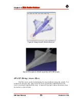
Figure 46: Awave Slicing option under the Geometry menu.
Figure 47: Awave slicing options for sample BWB model.
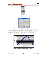
Once the parameters are set, click Start Slicing. This command also writes a file
to the directory of the vsp.exe named “slice.txt.” When the slice.txt file is opened, it will
list the area distribution in two columns: X and Area. These data may be ported to a
spreadsheet program such as Excel to create charts that visually show the area
distribution of the aircraft, as shown below:
0
100
200
300
400
500
600
700
800
900
1000
1
4
7 10 13 16 19 22 25 28 31 34 37 40 43 46 49 52
X-plane Coordinates
Ar
e
a
Figure 48: Area distribution results for sample BWB model.


