Chapter 8:
Main Toolbar Features
VSP User Manual
58
Version 1.7.92
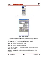
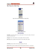
Figure 55
shows the interface used to define the structure and in particular the upper
skin thickness.
Default Element Size
: target edge size for the mesh
Thickness Scale
: Scale the thickness of all ribs, spars and skins
Section ID
: Which wing section to edit (1 of 2 in this case).
Edit Tabs
: Select which part to edit – ribs, spars, or skin
Export:
no to remove the skin from the exported mesh
Default thickness
: any area not covered by splice lines will get this thickness
Density
: density of skin material
Splice Lines
: Chord wise lines that define skin thickness
Splice Line ID
: Choose which splice line to edit
Splice Line Loc
: Location of line as a percentage of span (per section)
Splices
: Thickness definition points
Add Splice
: Press this button to add a splice, then click in the edit window below to
position splice. Hold left mouse button to move.
< >
: Changes which splice to edit
Delete
: Delete the current edit splice (in red)
Splice Edit Window
: Press left mouse button to select closest splice. Hold mouse
button to move the splice.
Thickness
: set thickness of current splice
Position
: set position of current splice (percent chord)
Export FEA Mesh
: press this button to perform intersection and meshing operations.
Depending on the element size, this could take several minutes or more.
Draw Mesh
: Display the final exported mesh. Turn off to restore the edit display.


