Chapter 9:
Modeling Example
VSP User Manual
76
Version 1.7.92
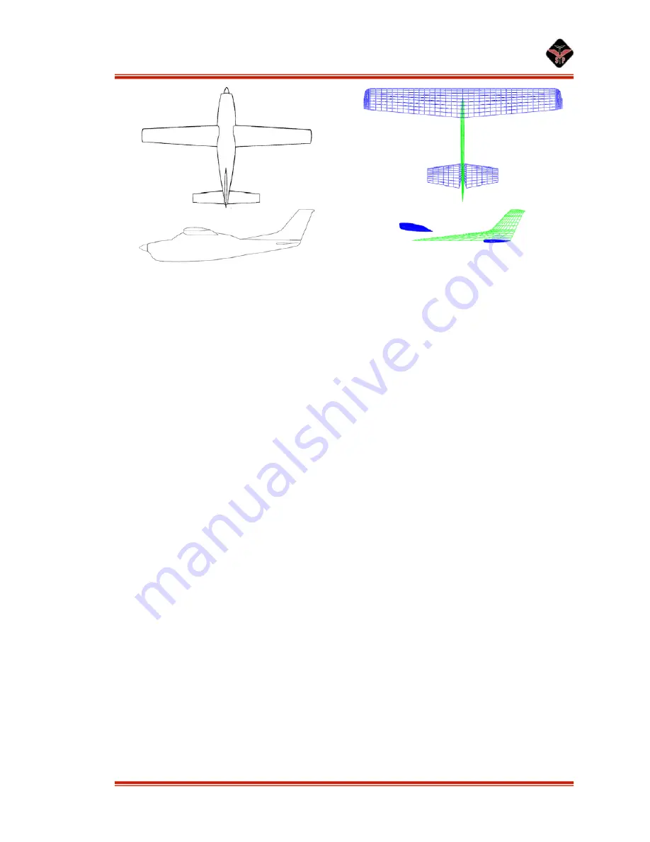
Figure 71: Top and profile views of Cessna 210 with main wing, vertical tail, and tailplane. Note the
pronounced extension of the vertical tail into the fuselage space; this will ensure a smooth transition
between surfaces when the fuselage is added.
Fuselage Layout
Now it is time to begin setting the fuselage. For a very high fidelity model, this
will be the most time consuming part.
First, set a background image of the side of the airplane. Then adjust the zoom,
and position of the model so the wing and horizontal tail line up correctly in the
background image. Now insert a fuselage. The view will jump, but just hit the side view
key again to line it up. Now set the length and forward and aft position of the fuselage.
Next set the nose of the part over the nose in the background image. It should now be the
proper length and in the proper location.
Editing Cross Sections
It is now time to edit the cross sections of the fuselage in order to line them up
over the background image. Start off by setting around 3 or 4 cross sections. Put them at
major spots like the fuselage/windshield junction, and the max fuselage height, etc. Then
switch to top view to set their heights. Cross section types can be changed to more
suitable shapes, like round box, or general, or even a fuselage file if one is available or
the user decides to create one. Finally, start adding more cross sections around the first
few to get the curves smoother. The more cross sections that are present, the more
accurate and smooth the fuselage will be. Note that the number of cross sections used
can quickly add up: to do a very high quality job of this Cessna, for example, would
require at least 20 fuselage cross sections to capture all of the curves of the aircraft.


