


AA21-450 Cabin PA System
SM34 Installation and Operation Manual Supplement
SM Supplement Rev: 1.02
Apr 21, 2009
Page 1
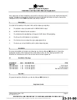
This supplement contains installation and operation information that is unique to the AA21-450 Cabin PA
system. Installation and operation information common to the AA21-400 base unit can be found in the
SM34
Installation and Operation Manual.
Section 1 Description
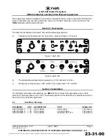
The AA21-450 is identical to the AA21-400 with the following exceptions:
a)
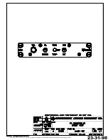
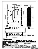
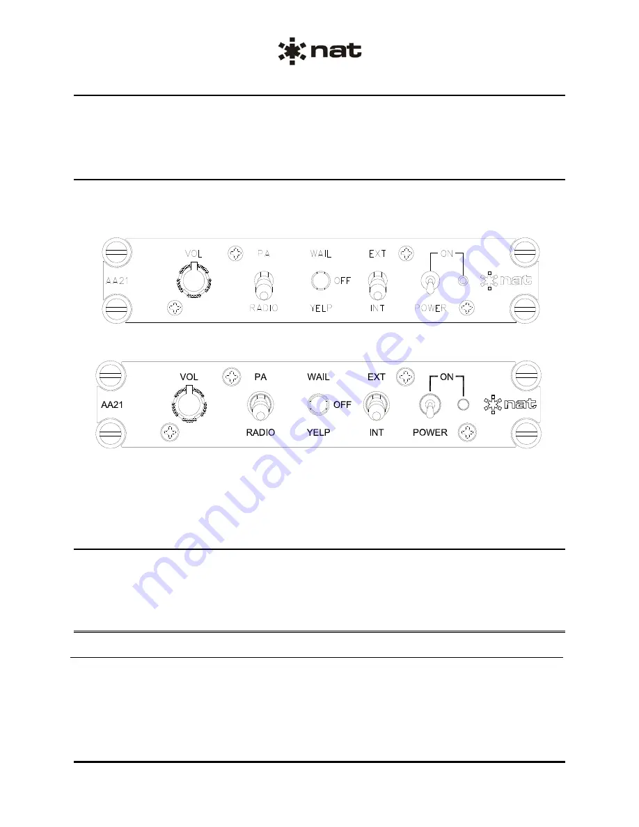
Changes to the faceplate text can be seen by comparing Figure 1 to Figure 2.
Figure 1: AA21-400
Figure 2: AA21-450
b)
The backlighting subassembly is powered by +5 Vdc instead of +28 Vdc.
c)
All instances of signal name “+28V LIGHTS” are replaced with “+5V LIGHTS”.
Section 2 Installation
For installation information and drawings, see
SM34
Section 2. Select the appropriate revision of the
drawing for the serial number of the unit. The drawings specific to this derivative are listed below and can
be found at the end of this supplement.
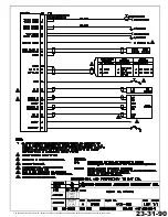
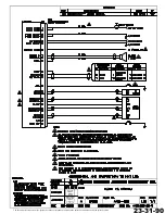
2.2 Installation
Drawings
DOCUMENT
REV.
DESCRIPTION
TYPE
SERIAL NO.
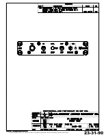
AA21\450\403-0
1.01
PA Controller
Interconnect
1220 and up
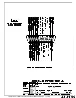
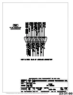
AA21\450\405-0
1.00
PA Controller
Connector Map
1220 and up
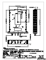
AA21\450\905-0
1.10
PA Controller
Faceplate Sht 1 of 3
1220 and up
ENG-FORM: 810-0111.DOT
CONFIDENTIAL AND PROPRIETARY TO NORTHERN AIRBORNE TECHNOLOGY LTD.
23-31-90
The document reference is online, please check the correspondence between the online documentation and the printed version.