26
Gas Furnace
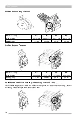
On Non-Condensing Furnaces
Furnace Size (Btuh)
28k
38k
51k
64k
Opens (in w.c.)
-0.55 +/- .05
-0.55 +/- 0.05
-0.55 +/- 0.05
-.055 +/- 0.05
Closes (in w.c.)
-0.65 Max
-0.65 Max
-0.65 Max
-0.65 Max
On Condensing Furnaces
Furnace Size (Btuh)
25k
32k
43k
50k
Opens (in w.c.)
-0.9 +/- 0.05
-0.9 +/- 0.05
-0.9 +/- 0.05
-0.7 +/- 0.05
Closes (in w.c.)
-1.05 Max
-1.05 Max
-1.05 Max
-1.05 Max
Collector Box Pressure Switch (Condensing Furnaces Only)
The collector box pressure switch is a safety used to prove that condensate is draining from the
secondary heat exchanger and front collector box.
0.55”
WC
On Condensing furnaces
BTU Size
25K
32K
43K
50K
Opens ("wc)
-.9 +/- .05
-.9 +/- .05
-.9 +/- .05
-.7 +/- .05
Closes ("wc)
-1.05 Max
-1.05 Max
-1.05 Max
-1.05 Max
Collector Box Pressure Switch (Condensing Furnaces Only)
The collector box pressure switch is a safety used to prove that condensate is draining from the secondary heat exchanger
and front collector box.
The Pressure Switch is normally open
BTU Size
25K
32K
43K
50K
Opens ("wc)
-.2 +/- .05
-.3 +/- .05
-.3 +/- .05
-.6 +/- .05
Closes ("wc)
-.35 Max
-.45 Max
-.45 Max
-.75 Max
To check the pressure switch, first prove that the inducer assembly is pulling adequate static pressure at the pressure
switch tubing using a manometer.
To prove the pressure switch has welded closed, use an ohmmeter, and verify there is continuity across the terminals when
disconnected from the pressure switch tubing.
If the unit is experiencing faults with the pressure switch check for the following:
•
Proper venter motor operation with no obstructions in the housing.
•
Inspect the tubing for blockages, cracks, or other damage.
•
Check the ports on the venter housing for blockage with corrosion or debris.
•
Verify that the venter tubing is installed properly on the pressure switch (non-condensing models) (gray – negative
Summary of Contents for CPG41838-U
Page 2: ...2...
Page 5: ...5 Unit Dimensions Original R22 with Gas Heat A B Series 43...
Page 6: ...6 Original R22 with Electric Heat A B Series Unit Dimensions...
Page 7: ...7 Unit Dimensions Original R410A with Gas Heat B C D E Series...
Page 8: ...8 Unit Dimensions Original R410A with Electric Heat B C D E Series...
Page 9: ...9 Unit Dimensions U Series R410A 80 Gas Heat...
Page 10: ...10 Unit Dimensions U Series R410A up to 95 Gas Heat...
Page 11: ...11 Unit Dimensions U Series R410A Electric Heat...
Page 19: ...19 Gas Furnace 3 Remove the 11 screws 4 Remove the front furnace baffle...
Page 46: ...46 Chassis Cooling Section...
Page 79: ...79...


