32
Gas Furnace
Gas Valve
The gas valve receives a gas supply and regulates gas after a call for heat is initiated. In
both models the gas valve is located in the upper right-hand section of the furnace.
For Non-Condensing Models the gas valve is a slow opening valve that is energized by a 24
Volt signal sent from the DSI control board.
For Condensing Furnaces the gas valve immediately opens when it is energized by a 24 Volt
signal sent from the DSI control board.
If the unit is experiencing a spark without ignition check for the following:
• Gas valve power with a voltmeter verify 24 Volts at the gas valve terminals.
• Gas pressure - Check the inlet and outlet (manifold) pressure. Both valves allow
access to both the inlet and outlet pressure with an allen wrench. Be sure to shut the
gas supply valve off when installing a manometer onto the gas valve.
Pressure requirements:
• Required 3.5”w.c. Natural Gas Outlet Manifold Pressure (10” w.c. LP)
• Minimum of 5” w.c. Natural Gas Inlet (11” w.c. LP)
• Maximum of 10” w.c. Natural Gas Inlet (14” w.c. LP)
If the inducer motor is not running, verify you have a call for heat with a flashing green light. Then verify that the inducer
relay on the control board has closed by checking for the appropriate voltage between the IND and Neutral terminals on
the DSI control board.
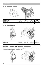
Inducer Orifice (Condensing Furnaces Only)
The inducer orifice is installed on the inlet of the inducer assembly and affects the overall system pressure.
To access the orifice, you will need to remove the entire inducer assembly.
BTU Size
25K
32K
43K
50K
Orifice Size
0.462
0.5265
0.62
0.81
Gas Valve
The gas valve receives a gas supply and regulates gas after a call for heat is initiated. In both models the gas valve is located
in the upper right-hand section of the furnace.
For non condensing models the gas valve is a slow opening valve that is energized from a 24 volt signal sent from the DSI
control board.
For condensing furnaces the gas valve
immediately opens when it is energized from a 24 volt signal sent from the DSI
control board.
If the unit is experiencing a spark without igni
�
on check for the following
•
Gas valve power, with a voltmeter verify 24 volts at the gas valve terminals
•
Gas pressure, Check the inlet and outlet (manifold) pressure. Both valves allow for access to the both the inlet and
outlet pressure which can be accessed with an allen wrench. Be sure to shut the gas supply valve o
ff
when
installing your manometer onto the gas valve.
Pressure requirements
•
Required 3.5”w.c. Natural Gas Outlet Manifold Pressure (10” w.c. LP)
•
Minimum of 5” w.c. Natural Gas Inlet *11” w.c. LP)
•
Maximum of 10” w.c. Natural Gas Inlet (14” w.c. LP)
Gas valve relay fault
If the control senses the gas valve as energized for more than one second when the control is n
ot a�
enmp
�
ng to energize
the gas valve, or the gas valve is sensed as not energized when it is supposed to be ineregizeds, then the control will locked
with the green LED o
ff
. The control assumes either the contacts of the relat driving the gas valve have welded shuit ir the
sensing circuit has failed. The venter motor is forced o
ff
to open the pressure witch to stop gas
fl
ow unless
fl
ame is present.
If the gas vlave was sensed as clesed when it should be openm and has not de-sengerized a
�
er the ventor motor was
shuto
ff
for 15 seconds, the n the ventor motor is re-energized to vent the unbeerned gas.
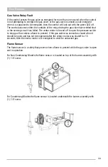
Flame Sensor
The
fl
ame sensor is a safety that proves when a
fl
ame is present while the gas
valve is open and in opera
�
on.
Summary of Contents for CPG41838-U
Page 2: ...2...
Page 5: ...5 Unit Dimensions Original R22 with Gas Heat A B Series 43...
Page 6: ...6 Original R22 with Electric Heat A B Series Unit Dimensions...
Page 7: ...7 Unit Dimensions Original R410A with Gas Heat B C D E Series...
Page 8: ...8 Unit Dimensions Original R410A with Electric Heat B C D E Series...
Page 9: ...9 Unit Dimensions U Series R410A 80 Gas Heat...
Page 10: ...10 Unit Dimensions U Series R410A up to 95 Gas Heat...
Page 11: ...11 Unit Dimensions U Series R410A Electric Heat...
Page 19: ...19 Gas Furnace 3 Remove the 11 screws 4 Remove the front furnace baffle...
Page 46: ...46 Chassis Cooling Section...
Page 79: ...79...


