43
Chassis (Cooling Section)
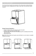
Once removed from the cabinet, all components for the cooling section including the blower
can be easily serviced. (Shipping Bolts are located on both sides of the cabinet and must be
removed).
Chassis Removal Instructions
• Remove the bottom filter access panel and control access panel.
• Remove 4 screws and slide-out air divider panel
• Disconnect both power and control molex plugs along with main drainpipe and secondary
drain. (not shown)
• Slide chassis forward
Note:
Only slide-out chassis out enough to access the blower if you do not plan on completely
removing from cabinet.
Summary of Contents for CPG41838-U
Page 2: ...2...
Page 5: ...5 Unit Dimensions Original R22 with Gas Heat A B Series 43...
Page 6: ...6 Original R22 with Electric Heat A B Series Unit Dimensions...
Page 7: ...7 Unit Dimensions Original R410A with Gas Heat B C D E Series...
Page 8: ...8 Unit Dimensions Original R410A with Electric Heat B C D E Series...
Page 9: ...9 Unit Dimensions U Series R410A 80 Gas Heat...
Page 10: ...10 Unit Dimensions U Series R410A up to 95 Gas Heat...
Page 11: ...11 Unit Dimensions U Series R410A Electric Heat...
Page 19: ...19 Gas Furnace 3 Remove the 11 screws 4 Remove the front furnace baffle...
Page 46: ...46 Chassis Cooling Section...
Page 79: ...79...


