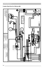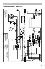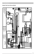
48
Chassis (Cooling Section)
The harnesses from both the 14270055 and 14270059 connect to the 5 pin motor speed
terminal board. The motor speed can be adjusted at this board. Each harness has a color that
matches up with a number on the board which determines motor speed.
Terminal
Wire Color
Speed/Torque
1
Red
High
2
Yellow
Med-High
3
Blue
Medium
4
Black
Med-Low
5
Orange
Low
Each speed tap is energized by a 24 Volt signal sent through a blower operation wire that
originates at the DSI control board.
• Orange = Heating and Fan Only operation
• Blue = Cooling operation
To check that the signal is coming from the control board properly measure for voltage at the
terminal board where the desired blower operation wire is located and the low voltage common
located at the transformer or the contactor coil.
Summary of Contents for CPG41838-U
Page 2: ...2...
Page 5: ...5 Unit Dimensions Original R22 with Gas Heat A B Series 43...
Page 6: ...6 Original R22 with Electric Heat A B Series Unit Dimensions...
Page 7: ...7 Unit Dimensions Original R410A with Gas Heat B C D E Series...
Page 8: ...8 Unit Dimensions Original R410A with Electric Heat B C D E Series...
Page 9: ...9 Unit Dimensions U Series R410A 80 Gas Heat...
Page 10: ...10 Unit Dimensions U Series R410A up to 95 Gas Heat...
Page 11: ...11 Unit Dimensions U Series R410A Electric Heat...
Page 19: ...19 Gas Furnace 3 Remove the 11 screws 4 Remove the front furnace baffle...
Page 46: ...46 Chassis Cooling Section...
Page 79: ...79...

