background image

National Cycle, Inc.

 PO Box 158 Maywood, IL 60153-0158 USA

P: 708-343-0400 / F: 708-343-0625 / E: info@nationalcycle.com

www.nationalcycle.com

©2021 National Cycle, Inc.

Page 01 of 13

10-118625-000   03/21

Thank you for purchasing a National Cycle product. Read these instructions carefully and thoroughly before beginning work. Dealers, if installing this 
windshield for a customer, please give them this manual upon completion. It contains information needed to properly maintain and use this product. 

Description:

Wash'n'Wipe Kit for N30214 
Full Size WIndshield

Model:

Polaris® Ranger Full Size, Round 
Frame Tube, Various Models 

Part Number:

N30214-WK

Installation Time:

60-90 min.

Quantum® is a registered trade-
mark of National Cycle Inc.

Assembly Instructions 
and Owner’s Manual


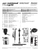
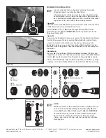
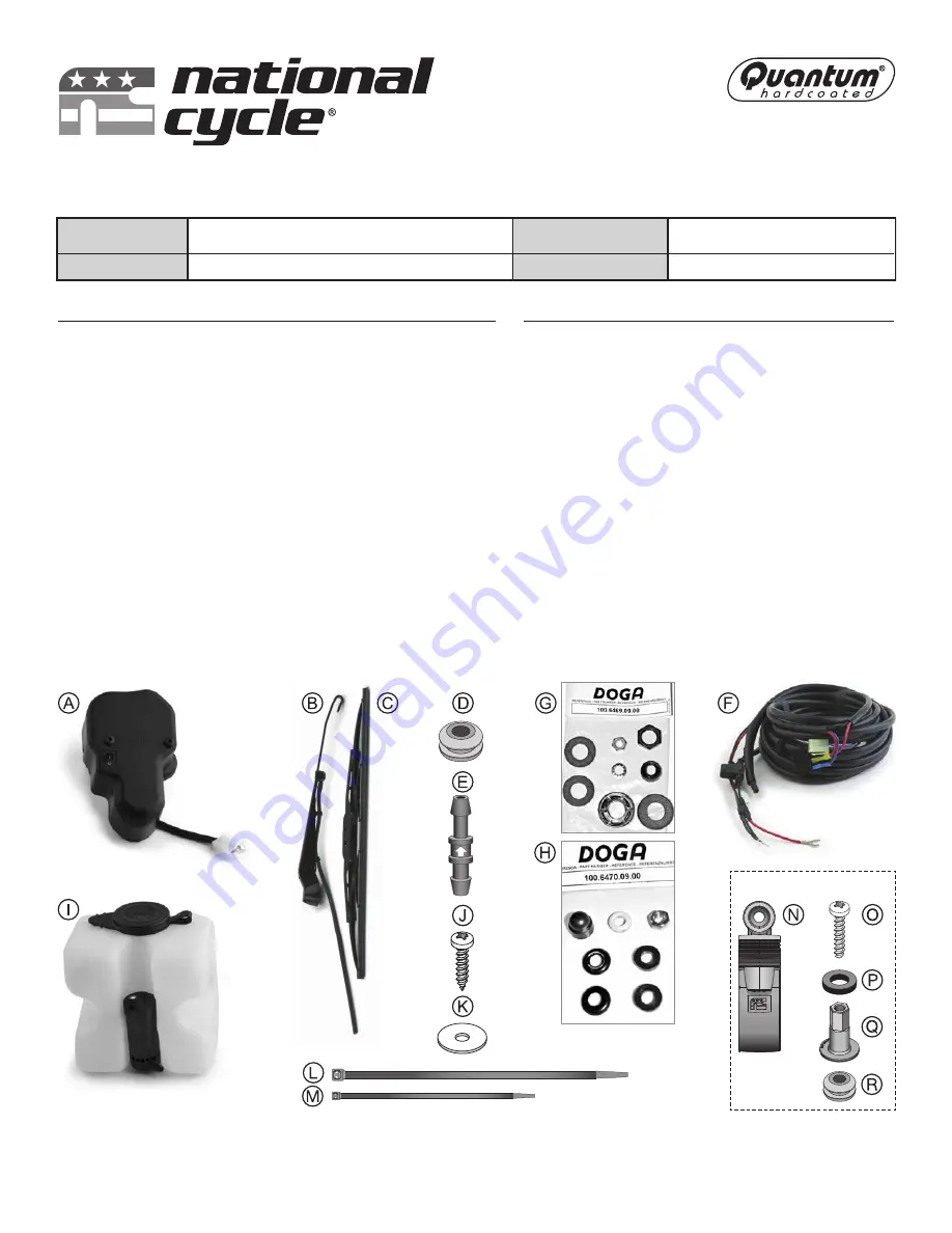
N30214-WK PARTS LIST 
ITEM   PART NO.               DESCRIPTION                                       QUANTITY


A

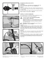
        80-875150-000       Wiper Motor Assembly with Switch                         1 

B

        80-875153-000       Wiper Assembly Arm, 350mm (14.00")                   1 

C

        80-875155-000       Wiper Assembly Blade, 400mm (15.75")                1 

D

        44-447167-000       Rubber Grommet; 1/4" I.D.                                     1 

E

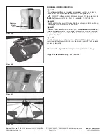
        44-441927-000       Inline Check Valve for Washer Tubing                    1 

F

        80-830326-000       Wire Harness and Switch                                        1 


G

        80-875156-000       Spindle Hardware Kit                                              1 

H

        80-875157-000       M8 Stud Hardware Kit                                             1 


I

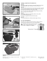
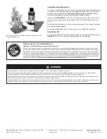
          44-442523-000       Reservoir & Pump Assembly                                  1 

J

         55-550260-000       Machine Screw, Panhead, Slotted, 12 x .75           2 

K

        49-490543-000       Flat Washer, .253 x .875 x .05                                2 

L

        44-448710-000       Wire Tie, 11.00"                                                       2 

M

        44-448726-000       Wire Tie, 7.50"                                                       10 


BAG#1368 
N

        44-449370-000       Clamp, Wraparound                                                1 

O

        55-563131-000       Machine Screw, Phillips, #12 x 1.25                       1 

P

        49-490355-000       Washer, Flat, Black                                                  1 

Q

        44-449380-000       Retaining Pin                                                           1 

R

        44-441165-000        Rubber Grommet; 5/16" I.D.                                   1

 
TOOLS REQUIRED FOR ASSEMBLY


Flat Blade Screwdriver 
#2 or #3 Phillips Screwdriver or Phillips Bit for Drill  
T-27 Torx Wrench 
10mm Wrench (or Adjustable Wrench) 
13mm Socket 
3/8" Wrench or Socket  
7/16" Wrench or Socket 
1/4" Hex Wrench 
Metal Scribe or Marker 
X-Acto® Knife, or similar  
Wire Cutters  
Power Drill with 3/4" (19mm) hole saw or step drill bit 
Small Drill Bits (1/16" or 3/32", 1/8") for pilot holes 
Torque Wrench

BAG#1368

Summary of Contents for Quantum hardcoated N30214-WK

Page 1: ...m 14 00 1 C 80 875155 000 Wiper Assembly Blade 400mm 15 75 1 D 44 447167 000 Rubber Grommet 1 4 I D 1 E 44 441927 000 Inline Check Valve for Washer Tubing 1 F 80 830326 000 Wire Harness and Switch 1 G 80 875156 000 Spindle Hardware Kit 1 H 80 875157 000 M8 Stud Hardware Kit 1 I 44 442523 000 Reservoir Pump Assembly 1 J 55 550260 000 Machine Screw Panhead Slotted 12 x 75 2 K 49 490543 000 Flat Wash...

Page 2: ...ions Black Negative Red Positive III Pump Switch for Washer Mounts to Dash Inside Cab I Motor Connector and Fluid Hose Installs to Motor II Grommet Seals 3 4 Hole IV Pump Connector and Fluid Hose Install to Fluid Reservoir and Pump Illustration A Figure 01 Figure 02 PREPARATION AND ELECTRICAL WIRING Figure 01 On the dashboard panel to the left of the speedometer are accessory switch covers Using a...

Page 3: ...position it inside the vehi cle s body under the dash on the driver s side as shown Using a marker mark inside the holes of the Reservoir s mounting tabs Figure 06 Using a 1 16 2mm drill bit drill two holes at the locations marked in Figure 5 Figure 07 Start one Machine Screw J and Flat Washer K into the right side mount tab of the Reservoir then Figure 08 guide it into the forward drilled hole in...

Page 4: ...ss components until they emerge under the dash above the cab s floorboards Figure 14 Move inside the cab and pull the wire tied Harness components until you can connect the Rubber Hose to the bottom of the Reservoir s Electrical Pump Then push the Nylon Quick Connector onto the two pins on top of the Reservoir s Electrical Pump Figures 15A 15B Pull the Wire Harness Terminal I single sheath with Sm...

Page 5: ...ector and connected Two Way Pump Switch III Temporarily remove the Pump Switch and thread the wiring under the hood toward the hole you cut in the dash panel s accessory switch cover in Figure 1 Figure 17 Move inside the vehicle s cab and secure the two Nylon Pin Connectors Figure 18 Reattach the Two Way Rocker Switch to the two Nylon Pin Connectors polarity doesn t matter and then push the Rocker...

Page 6: ...e terminal nut of the vehicle s battery with a Philips screwdriver or 10mm wrench Figure 21 Slip the Brass Open Ring Connector under the positive terminal nut and then tighten securely Figure 22 Use a Wire Tie M to organize and secure any slack coils of the Wire Harness and Figure 23 stow the excess coils under the left front wheel cover inside the engine compartment Figure 24 Close the vehicle s ...

Page 7: ...e Wrapround Clamp N Figure 26 If removing the Windshield loosen and remove the Panhead Philip Screws from the Wraparound Clamps securing Windshield to the vehicle frame Loosen the Velcro on the bottom section and carefully remove the Windshield making sure you don t lose the the Retaining Pins Spacing Washers or the cable guides Place the Windshield on the floor away from the vehicle Illustration ...

Page 8: ...rge Mounting Nut onto the Spindle Place the Small Rubber Washer Small Cup Washer with the cup facing the Windshield and Small Mounting Nut onto the M8 Stud The nut on the Spindle larger shaft needs to be torqued to 4 5 ft lbs 6 N m The nut on the stud smaller shaft needs to be torqued to 3 ft lbs 4 N m Finally place the Nylon Spindle Standoff onto the Motor s Spindle and the Black Nylon Nut Cover ...

Page 9: ...llation Instruction Sheet 10 118624 000 Need the instructions Go to www nationalcycle com and insert N30214 into the search box on the top right of the home page Click the product listing then click on the N30214 Installation Instructions PDF link Make sure you install the additional Wraparound Clamp from BAG 1368 as outlined on Page 07 Figure 32 In Figures 15A 15B previously you pulled the Wiring...

Page 10: ...h the Inline Check Valve E A little moisture on the Check Valve ends will make the hoses join easier The arrow on the Inline Check Valve E must point towards the Wiper Motor not towards the Fluid Reservoir Figure 37 Join the power connectors from the Wiper Motor and from Motor Connector Fluid Hose terminal I Tuck excess wiring behind the Wiper Motor assembly Figure 38 The completed Wiper Motor ins...

Page 11: ...re 40 The Wiper Motor has a on off Rocker Switch as shown Turn the switch on and verify that the Wiper works as expected Figure 41 The dash panel Rocker Switch installed in I PREPARATION AND ELEC TRICAL WIRING controls the fluid spray Momentarily hold the Switch in the on position to spray water from the Wiper Arm It should spray in four separate directions Figure 42 Now that you ve been testing y...

Page 12: ...rds the motor end of Wiper Arm to loosen blade To install a new Wiper Blade join the end of the Wiper Arm B to the Wiper Blade Place the J hook of the Arm over the Blade s plastic mounting clip until it clicks and locks into place Close the small access cover Figure 43 To remove the Wiper Arm B open the Wiper Arm cover and remove the Internal Tooth Lock Washer and Small Mounting Nut M8 Stud Hardwa...

Page 13: ...ing failure cosmetic wear and tear replacement of hardware or any consequential damages or expenses including labor cost of installation removal and or replacement inconvenience inbound freight expenses or damage to any other component of the vehicle or any other accessories Certain chemicals generally known as acidic hydrocarbons are known to cause polycarbonate damage and will not be covered und...

Reviews: