background image

EN

13

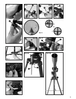
3. Accessory Tray

The accessory tray (No. 1 and 3, 10) should be attached to the center of 
the tripod brace (No. 1, 16) with the flat side down. The center hole in the 
tray should be fitted over the tripod brace retaining fittings. Mount the tray in 
place by turning it clockwise 60° (No. 5).

4. Telescope Tube

To mount the telescope tube (No. 1, 1) you undo the screw (No. 6, X) on 
the tube ring  (No. 1 and 2, 8) and open up the ring. Now you place the 
tube in the centre of ring and close the ring up. Now secure the mounting by 
tightening the screw. Position the tube, including the ring, with the objective 
opening facing north, and place it on the tripod head (No. 1, 9). Fasten the 
tube to the tripod head using the clamping screw (No. 7, X).

5. Eyepieces

Three eyepieces (No. 1 and 2, 18) and a diagonal mirror (No. 1 and 2, 19) 
are supplied with this telescope. The three eyepieces allow you to decide 
which magnification you want for your telescope. Before you insert the eye-
piece and the diagonal mirror, you must remove the dust protection cap from 
the eyepiece connection tube (No. 1, 6). Loosen the screw (No. 8, X) on 
the eyepiece connection tube and insert the diagonal mirror. Retighten the 
screw (No. 8, X) on the eyepiece connection tube.

Repeat the same process on the diagonal mirror screw (No. 9, X) and insert 
20 mm eyepiece in the diagonal mirror and retighten. 

Make sure that the eyepiece is pointing vertically upward. If it is not, loosen 
the screw (No. 8, X) on the eyepiece connection tube and rotate the diago-
nal mirror into the vertical position.

Risk of blindness

Never use this device to look directly at the sun or in the 
direct proximity of the sun. Doing so may result in a risk 
of blindness.

6. Viewfinder Assembly and Alignment

The viewfinder scope (No. 1 and 2, 2) and its holding device are 
preassembled. Push the foot of the viewfinder scope holding device 
completely into the base on the telescope tube (No. 10). The holding device 
will click into place. Make sure that the viewfinder scope lens (No. 10, X) 
faces the barrel opening (No. 1, 4). 

There are two black clamping screws on the holding device (No. 1, 3) plus a 
silver spring-loaded counter screw. Tighten the black clamping screws until 
you feel resistance. This affixes the viewfinder scope barrel in place. 

Before you start any observation, it is essential to adjust the viewfinder 
scope. The viewfinder scope and main telescope must be positioned identi-
cally in order to make observations with your telescope.

HINT

Insert the 20 mm eyepiece in the diagonal mirror and align 
the main telescope with an easily identifiable terrestrial 
object (No. 11, A). The object should be at least 200–300 
metres away. Position the telescope so that the object 
appears in the center of the eyepiece's field of vision. The 
image should appear vertical but inverted.

i

Follow the hint above. Once the telescope is aligned, look through the 
viewfinder scope. The image should be vertical and not inverted. To align 
the viewfinder scope, turn one of the two adjustment screws (No. 1, 3) until 
the image appears exactly the way it does through the telescope's eyepiece 
(No. 11, B). 

To focus the viewfinder scope, turn the viewfinder's front lens barrel (No. 10, 
X) left or right until the picture appears sharp and clear. 

7. Protection Caps

In order to protect the inside of your telescope from dust and dirt, the barrel 
opening (No. 1 and 12, 4) is protected by a dust protection cap (No. 12, 
X).  Before you begin observing with your telescope,  remove the cap from 
the opening. 

8. Flexible Shafts 

To ease precise adjustment of the declination and right ascension axes, 
install the flexible shafts (No. 1 and 3, 14 and 15) in the holding devices of 
both axes provided for the purpose (No. 13, X and Y).

The long flexible shaft should be mounted parallel to the telescope barrel 
(No. 1, 14). Secure it in place with the provided clamping screw in the 
axis notch. The short flexible shaft (No. 1, 15) should be mounted laterally. 
Secure it in place with the provided clamping screw in the axis notch.

Your telescope is now ready for use. 

Part II—Handling

Telescope Mount

Your telescope mount is of a new type that allows you to make two different 
types of observations:

A. Azimuth

, ideal for terrestrial use

B. Parallactic

, ideal for celestial observation

A. In azimuth use:

The telescope is moved horizontally and vertically.

1. Undo the polar vertical clamping screw (No. 14a, X) and lower the incline 
plate (No. 1, 17; No. 15, B) until it is horizontal (all the way to the stop). 
Retighten the polar vertical clamping screw.

2. Undo the vertical clamp (No. 15, A) and move the telescope until it hori-
zontal. Then retighten the vertical clamp. The telescope can now be moved 
horizontally and vertically using the flexible shafts (No. 1, 14 and 15; No. 
14, D and E).

B. In parallactic use:

2. Night Use

A dark site is very important for observation at night as light interferes with 
observation focus and detail visibility.  

Allow your eyes to adjust to the darkness after leaving a lighted room. After 
about 20 minutes you can begin celestial observation.  

Do not use the telescope within an enclosed space. Position your telescope 
and accessories in place outside about 30 minutes before observing to 
ensure temperature compensation in the telescope tube. Make sure the 
telescope is on a flat, stable surface.

3. Alignment—Basic Siting

Undo the polar vertical clamping screw (No. 14a X) and move the incline 
plate (No. 1, 17; No. 15, B) to the latitude of your location using the latitude 
adjustment rod as a rough guide. Turn the tripod so that the N mark faces 
north. The top of the incline plate should also face north (No. 14b). The 
latitude adjustment rod (No. 14a, Y) should point south. 

4. Setting Latitude

Determine the latitude of your location using a street map, atlas or the 
Internet. Germany is between 54° (Flensburg) and 48° (Munich) degrees 
of latitude.   

Undo the polar vertical clamping screw (No. 14a, X) and move the incline 
plate (No. 1, 17; No. 15, B) until the number on the latitude adjustment rod 
(No. 14a, Y) matches that of your location.

5. Final Alignment

Turn the declination axis (No. 15, C), including the telescope, 90°. 

Place the tube with the correct orientation into the holder and tighten the 
clamping screw. The telescope eyepiece should now point to the ground, 
and the lens should point to the sky. Undo the polar vertical clamping screw 

Summary of Contents for 70/900

Page 1: ...0 900 Multi Purpose Montierung Multi Purpose Mount Art No 90 71000 Bedienungsanleitung Operating instructions Mode d emploi Handleiding Istruzioni per l uso Instrucciones de uso Instrukcja obs ugi EN...

Page 2: ...cet apparareil directement ou proximit du soleil Veillez y particuli rement lorsque l appareil est utilis par des enfants Il existe un DANGER DE PERTE DE LA VUE Tenez le mat riel d emballage sacs en p...

Page 3: ...3 DE Bedienungsanleitung 6 EN Operating instructions 12 FR Mode d emploi 16 NL Handleiding 20 IT Istruzioni per l uso 24 ES Instrucciones de uso 28 PL Instrukcja Obs ugi 32 RU 36...

Page 4: ...ary depending on the model Les accessoires peuvent varier en fonction du mod le Accessoires kunnen vari ren afhankelijk van het model Gli accessori possono variare a seconda del modello Los accesorios...

Page 5: ...No 4 No 7 X No 10 No 12 B No 11 No 6 X No 5 No 13 X No 9 No 8 X X X No 14a X Y No 14b X Y A 11 5...

Page 6: ...No 16 No 17 No 15 A C B D E F 6...

Page 7: ...No 18 No 19 X 18 7 f 20 mm f 12 5 mm f 4 mm No 20 No 21 No 22 No 23 The Moon Orion Nebula M42 Ring Nebula in Lyra constellation M57 Dumbbell Nebula in the Vulpecula Fox constellation M27 20 18 19...

Page 8: ...instellrad Teil I Der Aufbau 1 Allgemeines Standort Bevor Sie mit dem Aufbau beginnen w hlen Sie einen geeigneten Standort f r Ihr Teleskop Es wird Ihnen helfen wenn Sie dieses Ger t an einem Ort aufb...

Page 9: ...e Befestigung erfolgt mit einer Klemmschraube an der vorgesehenen Einkerbung der Achse Ihr Teleskop ist nun einsatzbereit TEIL II Die Handhabung 1 Die Montierung Ihr Teleskop ist mit einer neuartigen...

Page 10: ...ind und je nach Jahreszeit Datum und Uhrzeit ihre Position am Himmel ver ndern Die Ausnahme bildet der Polarstern Durch ihn verl uft die verl n gert gedachte Polachse der Erde Er bildet den Ausgangspu...

Page 11: ...e Am 12 Juli 1764 ent deckte Charles Messier diese neue und faszinierende Klasse von Objekten Wir sehen dieses Objekt fast genau von seiner quatorialebene W rde man den Dumbbellnebel von einem der Pol...

Page 12: ...xample Accessories may vary depending on the model Parts No 1 3 B Telescope tube C Viewfinder scope D Adjusting screws viewfinder E Barrel opening F Objective G Eyepiece connection tube H Focus wheel...

Page 13: ...t does through the telescope s eyepiece No 11 B To focus the viewfinder scope turn the viewfinder s front lens barrel No 10 X left or right until the picture appears sharp and clear 7 Protection Caps...

Page 14: ...red picture size i 9 Find a Star Initially it will be difficult for you to find your bearings in the firmament since the stars and the constellations are always moving and according to the season date...

Page 15: ...s object almost directly from its equatorial plane If we could see the Dumbbell Nebula from one of its poles we would probably see the shape of a ring something very similar to what we know as the Rin...

Page 16: ...re du tube F Objectif G Rallonge pour oculaire H Vis d ajustement microm trique I Fixation tube J T te de tr pied montage 1 D p t pour accessoires 1 Clips de fixation tr pied 1 Support de fixation pla...

Page 17: ...neau Regardez travers le chercheur et fixez un objet lointain Tournez le support avant de la lentille dans un sens ou dans l autre jusqu ce que l objet apparaisse bien net Vissez maintenant le contre...

Page 18: ...t vous pouvez maintenant l aide des tiges souples poin ter l toile plus pr cis ment comme proc der au r glage de la nettet de l image avec la vis d ajustement microm trique illustration 16 B Par aille...

Page 19: ...L ascension droite 19h 59m heures minutes D clinaison 22 43 degr minutes Distance 1360 ann es lumi re de la terre La n buleuse M27 Dumbbell ou Hantelbebel dans le F chslein tait la premi re n buleuse...

Page 20: ...telschroeven Zoeker E Buisopening F Lens G Oculairsteunen H Focuswiel I Buisclip J Statiefkop Montering 1 Accessoirevak 1 Clips Statief 1 Fixeerstops Opslagvakje 1 Statiefpoten 1 Buigzame as voor hoog...

Page 21: ...10 X een tot twee slagen naar links U kunt nu de counterring apart instellen Kijk door de richttelescoop en focus deze op het object Draai de voorste lens linksom of rechtsom totdat het object scherp...

Page 22: ...met verschillen de brandpunten zijn nodig om verschillende vergrotingen te bewerkstelligen Begin elke waarneming met een ocu lair met een lage vergroting verder brandpunt 20mm i 9 Sterren zoeken In he...

Page 23: ...as de allereerste planetaire nevel die werd ontdekt Op 12 juli 1764 ontdekte Charles Messier deze nieuwe en fascinerende klasse hemellichamen Bij dit object kijken wij bijna precies op de evenaar Zoud...

Page 24: ...tivo di bloccaggio verticale B Piastra inclinabile C Asse di declinazione D Asta flessibile per l inseguimento E Asta flessibile asse di declinazione F Manopola della messa a fuoco Parte I Montaggio 1...

Page 25: ...a sull apposita scanalatura dell asse L asta pi corta No 1 15 viene montata lateralmente Fissare l asta con la vite di bloccaggio posta sull apposita scanalatura dell asse Parte II Uso 1 Montatura Il...

Page 26: ...costel lazioni e le collocazioni di alcune stelle visibili tutto l anno Ad ogni modo la posizione degli astri dipende dalla data e dall orario Puntando il telescopio su una di queste stelle si pu nota...

Page 27: ...o Nessuna immagine Rimuovere il coperchietto protettivo dall apertura dell obiettivo Immagine sfocata regolare la messa a fuoco agendo sulla manopola Mancata regolazione equilibrio termico messa a fuo...

Page 28: ...dera vertical B Base de inclinaci n C Eje de declinaci n D Ajuste del eje flexible E Eje flexible eje de declinaci n F Rueda de enfoque Parte I Instalaci n 1 General Emplazamiento Antes de comenzar a...

Page 29: ...ontal y vertical 1 Afloje el tornillo de ajuste de la vertical polar 14 bis ilustraci n X y baje la placa de inclinaci n hasta que est en posici n horizontal el tope Vuelva a apretar el tornillo de fi...

Page 30: ...resante y esperamos con xito se reco mienda que guarde el telescopio en un lugar seco y bien ventilado En algunos telescopios el tr pode y la montura se pueden separar f cilmente Los ajustes en el mon...

Page 31: ...sono dispo nibili presso il servizio di smaltimento comunale o l Agenzia per l ambiente locale Per lo smaltimento dell apparecchio osservare le disposi zioni di legge attuali Le informazioni su uno sm...

Page 32: ...f Obiektyw g Nasadka okulara h Stopie ustawienia ostro ci i Zacisk tubusu j G owica statywu monta 1 P ka na osprz t 1 ruby ustalaj ce statyw 1 Umocowanie reguluj ce p ka 1 N ki statywu 1 Wa gi tki do...

Page 33: ...zamontowa r wnolegle do tubusu teleskopu Umocowanie nast puje za pomoc ruby zaciskowej na przewidzianym do tego karbie osi Kr tki gi tki wa rys 1 15 nale y zamontowa z boku Umocowanie nast puje za po...

Page 34: ...i wa rys 15 D osi rektascencji i Pa stwa teleskop b dzie pod a za pozornym torem lotu tej gwiazdy 10 Osprz t Pa stwa teleskop jest podstawowo wyposa ony w trzy okulary rys 2 18 Przez wymian okular w o...

Page 35: ...ryw przeciwpy ow z wlotu obiektywu Nieostry obraz uregulowa ostro pier cieniem ogniskuj cym Niemo liwe ustawienie odczeka wyr wnanie temperatury ostro ci ok 30 min Z y obraz nie obserwowa nigdy przez...

Page 36: ...36 No 1 3 B C D E F G H I J 1 1 1 1 1 1 1 1 1 1 2 1 5 No 15 A B C D E F 5 1 16 4 1 4 11 i 1 3 10 1 16 60 5 1 1 6...

Page 37: ...37 RU 7 1 2 18 1 2 19 1 6 3 8 9 20 8 10 1 3 20 1 200 300 i 10 12 13 1 14 1 15 1 Monta A B A 1 14 2 15 1 14 15 B 20 14 15b N 15b 14 Y 55 59 56 43 4 14 14 Y 55 15...

Page 38: ...ve com anonymous user select i 1 8 16 17 15d 15 15f 20 i 15d 2 18 1 5x 900 mm 20 mm 45X 67X 900 mm 12 mm 75X 112X 900 mm 4 mm 225X 337X 2 18 19 8 1 6 2 20 9 3 476 384 400 29 5 709 42 05 35 05 22 1 344...

Page 39: ...39 RU M27 12 1764 M57 3 www bresser de warranty 49 0 2872 80 74 210...

Page 40: ...Yellow Border Design are trademarks of the National Geographic Society used under license All rights reserved Visit our website www nationalgeographic com ANL9071000MSP0514NG Irrt mer und technische...

Reviews: