Chapter 2
Configuration and Installation
© National Instruments Corporation
2-17
SCXI-1100 User Manual
Open Thermocouple Detection
For the SCXI-1100 to be able to detect open thermocouples, you must properly connect your
signals as explained in the previous section.
When the thermocouple opens, the PGIA bias currents charge the internal parasitic capacitors,
driving the PGIA inputs and output to saturation. Because it is not possible to predict the
direction of the bias currents, the PGIA can saturate to either the positive or negative rail. This is
open thermocouple detection.
Because the PGIA has low bias currents, the charging of the stray capacitances, and therefore
saturation, can be a slow process. It is best to have a self-test scan to check for open
thermocouples. Perform this self-test scan with the SCXI-1100 gain set to a minimum of 100
and the scan at a maximum rate of 15 Hz when you are in full bandwidth or in the 10 kHz filter,
and 3.5 Hz when you are in the 4 Hz filter. You can then execute this scan at regular intervals to
verify that all the thermocouples are connected. Saturation or a positive or negative reading
outside the expected range indicates an open thermocouple.
Analog Output
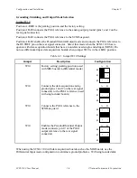
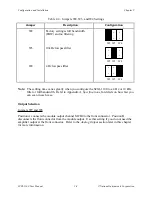
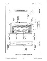
You can connect MCH0+ and MCH0- to the front connector to pins A8 and A7, respectively, via
internal jumpers as described in the Output Selection section earlier in this chapter. When you
do not need the module output at the front connector, place jumpers W7 and W8 in position B,
thus connecting pins A8 and A7 of the front connector to the module analog ground. This
connection reduces the amount of noise and stray capacitance coupling from the amplifier output
to its inputs, improving the settling time performance. In addition to the analog output, pin A6
connects to the SCXIbus guard.
Connector-and-Shell Assembly
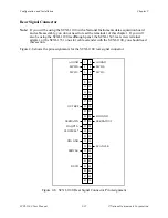
Two types of signal connectors are available to connect the signals to the SCXI-1100. The first,
the SCXI-1310 96-pin connector-and-shell assembly, is available in a kit listed in the Optional
Equipment section in Chapter 1, Introduction. The connector has eyelet ends for easy hook-and-
solder wire connection. With this kit, you can build your own signal cable to connect to the
SCXI-1100 inputs. After you have built the cable, use the shell to cover and protect the
connector.
Perform the following steps to build and mount the connector-and-shell assembly to your SCXI
module:
1.
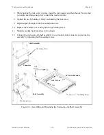
Refer to Figure 2-6 and the diagram included with your SCXI-1310 kit to build the
connector-and-shell assembly.
2.
Turn off the computer that contains your plug-in board or disconnect the board from your
SCXI chassis.
3.
Turn off your SCXI chassis.
4.
Slide the module out of the chassis.
5.
Remove the module cover. Refer to Figure 2-6 as you complete the remaining steps.
6.
Place one jack screw as indicated in Figure 2-6.


