Appendix E
SCXI-1100 Cabling
© National Instruments Corporation
E-5
SCXI-1100 User Manual
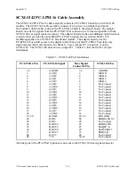
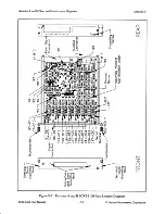
SCXI-1342 PC-LPM-16 Cable Assembly
The SCXI-1342 PC-LPM-16 cable assembly connects a PC-LPM-16 board to an SCXI-1100
module. The SCXI-1342 cable assembly consists of two pieces–an adapter board and a
50-conductor ribbon cable connects the PC-LPM-16 board to the adapter board. The adapter
board converts the signals from the PC-LPM-16 I/O connector to a format compatible with the
SCXI-1100 rear signal connector pinout. The adapter board also has an additional male breakout
connector that provides the unmodified PC-LPM-16 signals for use with an SCXI-1180
feedthrough panel or an SCXI-1181 breadboard module. The adapter board gives the
PC-LPM-16 board full access to the digital control lines, but the PC-LPM-16 can take only
single measurements and cannot scan channels. Leave jumper W1 in position A on the
SCXI-1342. The SCXI-1100 does not use jumper W1. Table E-3 lists the SCXI-1342 pin
translations.
Table E-3. SCXI-1342 Pin Translations
PC-LPM-16 Pin
PC-LPM-16 Signal
Rear Signal
Connector Pin
SCXI-1100 Use
1-2
AIGND
1-2
AOGND
3
ACH0
3
MCH0+
4
ACH8
4
MCH0-
5
ACH1
5
MCH1+
6
ACH9
6
MCH1-
7
ACH2
7
No Connect
8
ACH10
8
No Connect
9
ACH3
9
No Connect
10
ACH11
10
No Connect
11
ACH4
11
No Connect
12
ACH12
12
No Connect
13
ACH5
13
No Connect
14
ACH13
14
No Connect
15
ACH6
15
No Connect
16
ACH14
16
No Connect
17
ACH7
17
No Connect
18
ACH15
18
No Connect
19, 50
DGND
24, 33
DIG GND
28
DIN6
26
SERDATOUT
29
DIN7
28
No Connect
34
DOUT4
25
SERDATIN
35
DOUT5
27
DAQD*/A
36
DOUT6
29
SLOT0SEL*
37
DOUT7
37
SERCLK
46
OUT2
46
No Connect
49
+5 V
34-35
No Connect
All other pins of the PC-LPM-16 pinout are not sent to the SCXI-1100 rear signal connector.


