Chapter 2
Configuration and Installation
© National Instruments Corporation
2-9
SCXI-1100 User Manual
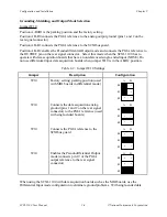
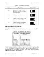
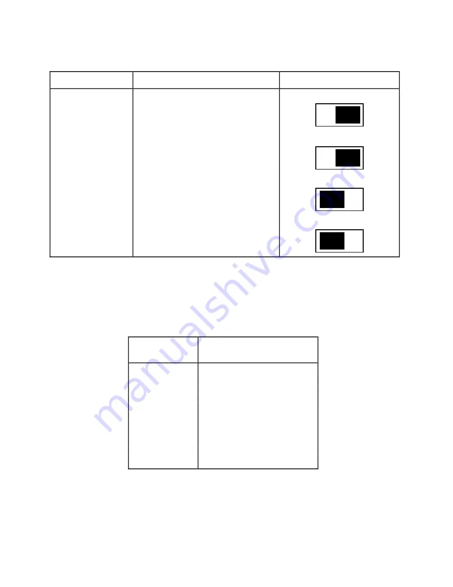
Table 2-5. Jumpers W7 and W8 Settings
Jumper
Description
Configuration
W7
W8
Factory setting; parking position.
Disconnects the front connector from
the module output
Factory setting; parking position
•
•
•
A B
•
•
•
A B
W7
Amplifier Output is connected to the
front connector OUTPUT pin
•
•
•
A B
W8
Amplifier Reference is connected to
the front connector AOREF pin
•
•
•
A B
Input Filtering and Current Loop Receivers
If you need input filtering, pads in which you can insert a capacitor are available at each input
channel. Table 2-6 shows which capacitor reference designator corresponds to which input
channel.
Table 2-6. User-Defined Input Filter Capacitors
Input Channel
Spare Capacitor Reference
Designator
0
C1
1
C5
2
C4
3
C2
4 through 7
C10 through C7 respectively
8 through 11
C16 through C13 respectively
12 through 15
C22 through C19 respectively
16 through 19
C30 through C27 respectively
20 through 23
C38 through C35 respectively
24 through 27
C44 through C41 respectively
28 through 31
C50 through C47 respectively
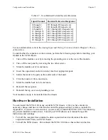
In addition, pads are available for transforming individual channels to current-to-voltage
converters. National Instruments manufactures an SCXI process-current pack, which consists of
a package of four 249
Ω
, 0.1%, 5 ppm/
°
C, 1/4 W resistors. The part number for this kit is in the
Optional Equipment section of Chapter 1, Introduction. Table 2-7 shows the input channels and
their corresponding resistor reference designators.

