Chapter 2
Configuration and Installation
© National Instruments Corporation
2-13
SCXI-1100 User Manual
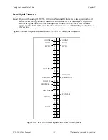
Front Connector Signal Descriptions
Pin
Signal Name
Description
A1
+5 V
+5 VDC Source – Used to power the temperature
sensor on the terminal block. 0.2 mA of source not
protected.
A2, A5, A16,
CGND
Chassis Ground – Tied to the SCXI chassis.
A24, A32
A3
MTEMP
Multiplexed Temperature Sensor – Connects the
temperature sensor to the output multiplexer.
A4
DTEMP
Direct Temperature Sensor – Connects the
temperature sensor to the MCH1+ signal when the
terminal block is configured for direct temperature
connection.
A6
GUARD
Guard – Connected to the SCXIbus guard.
A7
AOREF
Analog Output Reference – Connected to the
MCH0- signal as described in the Analog
Configuration section.
A8
OUTPUT
Output – Connected to the MCH0+ signal as
described in the Analog Configuration section.
B1-B32
CH31- through CH0-
Negative Input Channels – Negative input channels
to the PGIA.
C1-C32
CH31+ through CH0+
Positive Input Channels – Positive input channels to
the PGIA.
The signals on the front connector are all analog but can be divided into three groups–the analog
input channels, the temperature sensor, and the analog output channel.
Analog Input Channels
Columns B and C constitute the analog input channels for the multiplexed PGIA inputs. The
inputs are configured in Differential mode, hence you should ground reference the measured
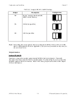
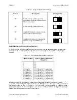
signal if it is floating. If the measured signals are floating, connect jumper W1 (position 2-3) to
produce a DC path for the input bias currents; otherwise, the PGIA bias currents charge up stray
capacitances, resulting in uncontrollable drift and possible saturation. Figure 2-3 illustrates how
to connect a ground-referenced signal. Figure 2-4 illustrates how to connect a floating signal.
Figure 2-5 shows how to connect AC-coupled signals.

