Configuration and Installation
Chapter 2
SCXI-1100 User Manual
2-20
© National Instruments Corporation
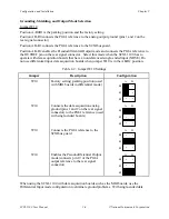
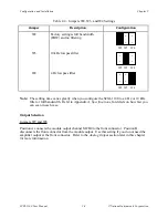
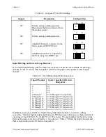
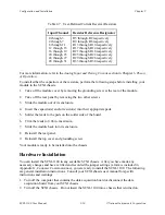
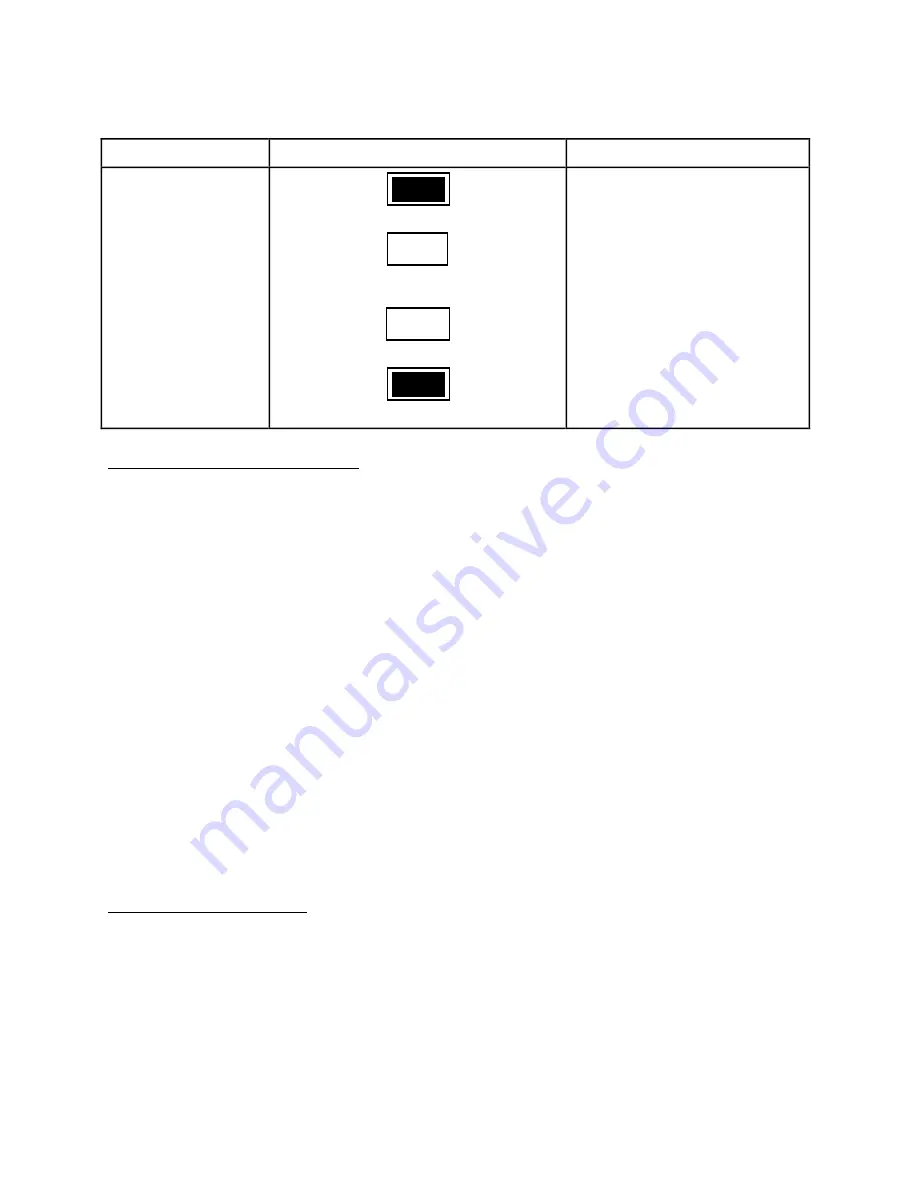
Table 2-8. Jumper Setting on the Terminal Block
Jumper
Position
Description
W1
W2
W1
W2
MTEMP
•
•
DTEMP
•
•
MTEMP
•
•
DTEMP
•
•
MTS mode selected; factory
setting; parking position
DTS mode selected
Terminal Block Signal Connection
To connect the signal to the terminal block, you will need Phillips-head number 1 and number 2
screwdrivers and a 0.125 in. flathead screwdriver. Use the following procedure (refer to the
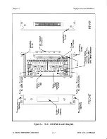
SCXI-1300 terminal block parts locator diagram in Figure 2-7):
1. Remove the grounding screw of the top cover with the Phillips-head number 1 screwdriver.
2. Snap out the top cover of the shield by placing the flathead screwdriver in the groove at the
bottom of the terminal block.
3. After loosening the strain-relief screws screws with the Phillips-head number 2 screwdriver,
slide the signal wires one at a time through the front panel strain-relief opening. Add
insulation or padding if necessary.
4. Connect the wires to the screw terminals by inserting the wires into the terminals and
tightening the screw without letting the wires slip out of the strain-relief bar.
5. Tighten the larger strain-relief screws.
6. Snap the top cover back into place.
7. Reinsert the grounding screw to ensure proper shielding.
8. Connect the terminal block to the SCXI-1100 front connector as explained in the Terminal
Block Installation section, the next section in this chapter.
Terminal Block Installation
To connect the terminal block to the SCXI-1100 front connector, perform the following steps:
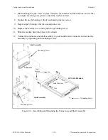
1. Connect the SCXI-1100 front connector to its mating connector on the terminal block.
2. Make sure that the SCXI-1100 top and bottom thumbscrews do not obstruct the rear panel of
the terminal block.
3. Tighten the top and bottom screws on the back of the terminal block to hold it securely in
place.

