Appendix C
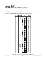
SCXIbus Connector
© National Instruments Corporation
C-3
SCXI-1100 User Manual
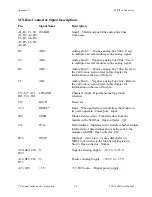
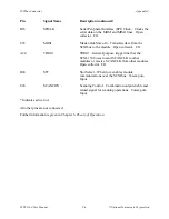
SCXIbus Connector Signal Descriptions
Pin
Signal Name
Description
A1, B1, C1, D1, GUARD
Guard – Shield and guard the analog bus lines
A2, D2, A3, B3,
from noise.
C3, D3, A4, D4,
A5, B5, C5, D5,
A6, D6
B2
AB0+
Analog Bus 0+ – Positive analog bus 0 line. Used
to multiplex several modules to one analog signal.
C2
AB0-
Analog Bus 0- – Negative analog bus 0 line. Used
to multiplex several modules to one analog signal.
B6
AB2+
Analog Bus 2+ – Positive analog bus 2 line. Refer to
the Calibration section later in this chapter for
information on the use of this pin.
C6
AB2-
Analog Bus 2- – Negative analog bus 2 line. Refer to
the Calibration section later in this chapter for
information on the use of this pin.
C13-C17, A21,
CHSGND
Chassis Ground – Digital and analog ground
B21, C21, D21
reference.
C18
RSVD
Reserved.
A19
RESET*
Reset – When pulled low, reinitializes the module to
its power-up state. Totem pole. Input.
B19
MISO
Master-In-Slave-Out – Transmits data from the
module to the SCXIbus. Open collector. I/O.
C19
D*/A
Data/Address – Indicates to the module whether address
information or data information is being sent to the
module on MOSI. Open collector. I/O.
D19
INTR*
Interrupt – Active low. Causes data that is on
MOSI to be written to the Slot-Select Register in
Slot 0. Open collector. Output.
A20, B20, C20, V-
Negative Analog Supply – -18.5 V to -25 V.
D20
A22, B22, C22
V+
Positive Analog Supply – +18.5 V to +25 V.
D22
A23, D23
+5 V
+5 VDC Source – Digital power supply.


