SCXI-1100 Cabling
Appendix E
SCXI-1100 User Manual
E-2
© National Instruments Corporation
•
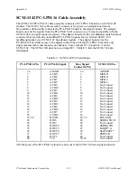
The SCXI-1340 has an extra male breakout connector for use with the SCXI-1180
feedthrough panel or additional modules or breadboards that need a direct connection to the
MIO board.
•
The SCXI-1340 rear panel gives both mechanical and electrical shielding.
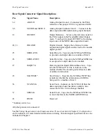
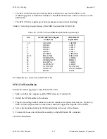
Table E-1 lists the pin equivalences of the MIO board and the SCXI-1100.
Table E-1. SCXI-1100 and MIO Board Pinout Equivalences
Pin
SCXI-1100 Rear Signal
Connector
MIO Board
Equivalent
1-2
AOGND
AIGND
3
MCH0+
ACH0
4
MCH0-
ACH8
5
MCH1+
ACH1
6
MCH1-
ACH9
19
OUTREF
AISENSE
24, 33
DIG GND
DIG GND
25
SERDATIN
ADIO0
26
SERDATOUT
BDIO0
27
DAQD*/A
ADIO1
29
SLOT0SEL*
ADIO2
36
SCANCLK
SCANCLK
37
SERCLK
EXTSTROBE*
43
RSVD
OUT1
No other pins are connected on the SCXI-1100.
SCXI-1340 Installation
Perform the following steps to install the SCXI-1340:
1. Make sure that the computer and the SCXI chassis are turned off.
2. Install the SCXI module in the chassis.
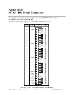
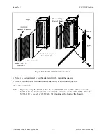
3. Plug the mounting bracket connector onto the module rear signal connector (see Figure E-1).
Make sure the alignment tab on the bracket enters the upper board guide of the chassis.
4. Screw the mounting bracket to the threaded strips in the rear of the chassis.
5. Connect the loose end of the cable assembly to the MIO board I/O connector.
Check the installation.

