background image

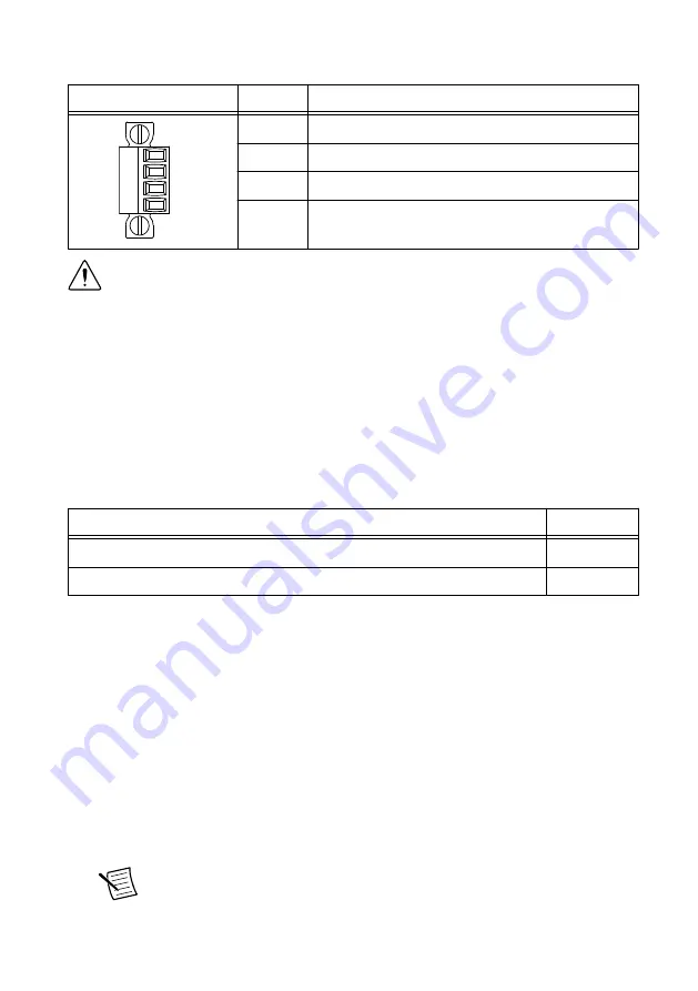
Table 1. Power Connector Pinout

Pinout

Pin

Description


V1
C
V2
C

V1

Primary power input

C

Common

V2

Secondary power input

C

Common

Caution


The C terminals are internally connected to each other, but are not

connected to chassis ground. This isolation is intended to prevent ground loops and
does not meet UL ratings for safety isolation. You can connect the C terminals to
chassis ground externally. Refer to the specifications on 

ni.com/manuals

 for

information about the power supply input range and maximum voltage from
terminal to chassis ground.

If you apply power to both the V1 and V2 inputs, the NI 9154 operates from the V1 input. If
the input voltage to V1 is insufficient, the NI 9154 operates from the V2 input.

The NI 9154 has reverse-voltage protection.

The following NI power supplies and accessories are available for the NI 9154.

Table 2. Power Accessories

Accessory

Part Number


NI PS-15 Power Supply, 24 VDC, 5 A, 100-120/200-240 VAC Input

781093-01

NI PS-10 Desktop Power Supply, 24 VDC, 5 A, 100-120/200-240 VAC Input 782698-01

MXI Express Port

You can use the MXI Express port on the NI 9154 to connect to a MXI Express chassis.
Complete the following steps to connect one or more NI 9154 to a MXI Express device.
1.

Make sure the MXI Express device is configured and powered off.

2.

Make sure the NI 9154 is powered off.

3.

Connect the NI 9154 to the MXI Express device using a x1 cable.

4.

Power on the MXI Express device.

5.

Power on the NI 9154.

The MXI Express LINK LED on the front panel of the NI 9154 lights green when
communication is established. The LINK LED lights yellow when communication is
broken or no cable is connected.

Note


The NI 9154 may not detect MXI Express devices connected while the

NI 9154 is powered on.

4

  | 

ni.com

  | 

NI 9154 User Manual

Summary of Contents for 9154

Page 1: ...g the NI 9154 You can connect the NI 9154 to a MXI Express host system and configure the powerup options using a MXI Express cable Connecting One or More NI 9154 Chassis to the MXI Express Host System...

Page 2: ...must detect all bus segments on the chassis side in order to configure the PCI hierarchy Powering connected chassis up or down while the host system is running can cause system hangs and data corrupt...

Page 3: ...OWER USER FPGA1 USER FPGA2 USER FPGA3 LINK LINK UPSTREAM DOWNSTREAM DO NOT SEPARATE CABLES WHEN ENERGIZED IN HAZARDOUS LOCATIONS MXI Express RIO NI 9154 OFF 1 2 1 Power Connector 2 MXI Express Upstrea...

Page 4: ...ower supplies and accessories are available for the NI 9154 Table 2 Power Accessories Accessory Part Number NI PS 15 Power Supply 24 VDC 5 A 100 120 200 240 VAC Input 781093 01 NI PS 10 Desktop Power...

Page 5: ...OWNSTREAM DO NOT SEPARATE CABLES WHEN ENERGIZED IN HAZARDOUS LOCATIONS 1 1 CMOS Reset Button CMOS Reset Button The NI 9154 has a CMOS reset button that you can use to reset the CMOS and the BIOS LEDs...

Page 6: ...f the electrode system of the facility Caution If you use shielded cabling to connect to a C Series module with a plastic connector you must attach the cable shield to the chassis grounding terminal u...

Page 7: ...that no C Series modules are in the NI 9154 before mounting it Dimensions The following figures show the front and side dimensions of the NI 9154 For detailed dimensional drawings and 3D models visit...

Page 8: ...top and the bottom of the NI 9154 for air circulation as shown in the following figure Figure 5 NI 9154 Cooling Dimensions 7 6 5 4 3 2 1 8 Cooling Outline 50 8 mm 2 00 in Cooling Outline 50 8 mm 2 00...

Page 9: ...ent temperature at each side of the NI 9154 63 5 mm 2 50 in from the side and 50 8 mm 2 00 in forward from the rear of the NI 9154 as shown in the following figure Figure 7 NI 9154 Ambient Temperature...

Page 10: ...unting kit because they are the correct depth and thread for the DIN rail clip Clipping the Device on a DIN Rail Complete the following steps to clip the NI 9154 on a DIN rail 1 2 1 Insert one edge of...

Page 11: ...ews with the panel mounting kit Tighten the screws to a maximum torque of 1 3 N m 11 5 lb in Note You must use the screws provided with the NI panel mounting kit because they are the correct depth and...

Page 12: ...ly on a flat rigid surface using the mounting holes in the NI 9154 What to Use NI 9154 M4 screw x2 user provided which must not exceed 8 mm of insertion into the NI 9154 What to Do Complete the follow...

Page 13: ...rer s declaration of conformity This system affords the user protection for electromagnetic compatibility EMC and product safety You can obtain the DoC for your product by visiting ni com certificatio...

Page 14: ...party legal notices in the readme file for your NI product Refer to the Export Compliance Information at ni com legal export compliance for the NI global trade compliance policy and how to obtain rel...

Reviews: