background image

USB-9211/9211A User Guide and Specifications

12

ni.com

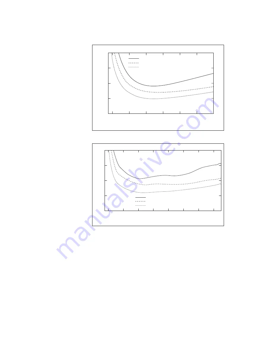
Figure 10.  

Type E and T Errors

Figure 11.  

Type J and N Errors

–200

0

200

400

600

800

1000

0

2

3

4

Max over Temp Range with Autozero
Max at Room Temp Range without Autozero
Typ over Temp Range with Autozero

Error (

°

C)

Measured Temperature (

°

C)

1

–200

0

200

400

600

800

1000

1200

0

1

2

3

4

Max over Temp Range with Autozero
Max at Room Temp Range without Autozero
Typ over Temp Range with Autozero

Error (

°

C)

Measured Temperature (

°

C)

Summary of Contents for 9211

Page 1: ... 9211 9211A data acquisition device provides a USB interface for four channels of 24 bit thermocouple inputs with integrated signal conditioning The NI USB 9211 consists of two components an NI 9211 module and a USB 9161 carrier as shown in Figure 1 The NI USB 9211A consists of two components an NI 9211 module and a USB 9162 carrier as shown in Figure 1 Figure 1 USB 9211 9211A Components NI 9211 U...

Page 2: ... the combined system may be limited Refer to the Specifications section for more details Hot Surface This icon denotes that the component may be hot Touching this component may result in bodily injury Caution Do not disconnect I O side wires or connectors unless power has been switched off or the area is known to be nonhazardous Caution Do not remove modules unless power has been switched off or t...

Page 3: ...devices and circuits connected to the module are properly insulated from human contact Caution When module terminals are live with hazardous voltages make sure that the terminals are not accessible by using the high voltage screw terminal enclosure Refer to the Assembling the High Voltage Screw Terminal Backshell section for more information Software Software support for your hardware depends on t...

Page 4: ...nd the USB 9161 9162 carrier are packaged separately Refer to Figure 3 while completing the following assembly steps 1 Make sure that no signals are connected to the NI 9211 module and the USB cable is not connected to the device 2 Remove the protective cover from the 15 pin DSUB connector Guide Location NI DAQmx Getting Started Guide Accessible from Start All Programs National Instruments NI DAQ ...

Page 5: ... 3 Module Installation 4 Squeeze the latches and insert the NI 9211 module into the carrier 5 Press firmly on the connector side of the NI 9211 module until the latches lock the module into place as shown in Figure 4 Figure 4 Locking Module into Place 6 Connect the USB cable to the assembled USB 9211 9211A 1 High Voltage Screw Terminal Backshell 1 ...

Page 6: ...to the USB 9211 9211A and the other end into an available USB port on the computer LED Indicator The LED indicator indicates device status Table 2 LED State Device Status LED State Device Status Not lit Device not connected or in suspend On not blinking Device connected but no module installed Single blink Operating normally Double blink Operating normally Quadruple blink Device error Refer to ni ...

Page 7: ...f the thermocouple TC The USB 9211 9211A also has a common terminal COM that is internally connected to the isolated ground reference of the module Caution The high voltage screw terminal backshell must be installed when using hazardous voltages 42 4 Vpk 60 VDC If you are unsure which of the thermocouple leads is positive and which is negative check the thermocouple documentation or the thermocoup...

Page 8: ...kshell must be installed when using hazardous voltages 42 4 Vpk 60 VDC Refer to Figure 7 while completing the following steps 1 Connect the leads to the screw terminal and secure with the strain relief 2 Finish by snapping the backshell around the connector Table 3 Terminal Assignments Module Terminal Signal 0 TC0 1 TC0 2 TC1 3 TC1 4 TC2 5 TC2 6 TC3 7 TC3 8 No connection 9 Common COM 0 1 2 3 4 5 6...

Page 9: ...he TC and COM terminals and between the TC and COM terminals Each channel is filtered and then sampled by a 24 bit analog to digital converter ADC There is a current source between the TC and TC terminals If an open thermocouple is connected to the channel the current source forces a full scale voltage across the terminals Effects of Source Impedance on Voltage Measurement Accuracy The resistors s...

Page 10: ...t errors depend in part on the thermocouple type the temperature being measured the accuracy of the thermocouple and the cold junction temperature Using the Autozero Channel The USB 9211 9211A has an internal autozero channel for measuring the offset error If the ambient temperature of the USB 9211 9211A is less than 15 C or more than 35 C use this channel to read the offset error The USB 9211 alw...

Page 11: ...ures account for gain errors offset errors differential and integral nonlinearity quantization errors noise errors and isothermal errors The figures do not account for the accuracy of the thermocouple itself Temperature gradients across the USB 9211 9211A terminals affect the cold junction temperature accuracy Refer to the Cold Junction Temperature Measurement Accuracy section for more information...

Page 12: ...0 1000 0 2 3 4 Max over Temp Range with Autozero Max at Room Temp Range without Autozero Typ over Temp Range with Autozero Error C Measured Temperature C 1 200 0 200 400 600 800 1000 1200 0 1 2 3 4 Max over Temp Range with Autozero Max at Room Temp Range without Autozero Typ over Temp Range with Autozero Error C Measured Temperature C ...

Page 13: ...thermal gradient generated across the terminals can cause the terminals of different channels to be at different temperatures so the resulting measurement creates errors not only in absolute accuracy but also in the relative accuracy between channels 200 0 200 400 600 800 1000 1200 0 1 2 3 4 Max over Temp Range with Autozero Max at Room Temp Range without Autozero Typ over Temp Range with Autozero...

Page 14: ...ect any extension wires to thermocouple wires use wires made of the same conductive material Specifications The following specifications are typical at 25 C unless otherwise noted All voltages are relative to COM unless otherwise noted Input Characteristics Number of channels 4 thermocouple channels 1 internal autozero channel 1 internal cold junction compensation channel ADC resolution 24 bits Ty...

Page 15: ... 60 Hz Overvoltage protection 30 V between any input and common Differential input impedance 20 MΩ Input current 50 nA Input noise 1 µVrms Gain error 0 05 max at 25 C 0 06 typ over temperature 0 1 max over temperature Offset error with autozeroing 15 µV typ 20 µV max Gain error from source impedance 0 05 ppm per Ω source impedance due to input impedance Number of Channels in Scan List Type of Meas...

Page 16: ...5 cm 5 51 in 3 37 in 0 99 in Weight Approx 350 g 12 3 oz Screw terminal wiring 12 to 24 AWG wire with 10 mm 0 39 in of insulation stripped from the end Torque for screw terminals 0 5 0 6 N m 4 4 5 3 lb in Safety Standards The USB 9211 9211A is designed to meet the requirements of the following standards of safety for electrical equipment for measurement control and laboratory use IEC 61010 1 EN 61...

Page 17: ... and electronics Isolation Channel to channel No isolation between channels Channel to earth ground Withstand 2 300 Vrms 5 seconds max Continuous 250 Vrms Measurement Category II Measurement Category II is for measurements performed on circuits directly connected to the electrical distribution system This category refers to local level electrical distribution such as that provided by a standard wa...

Page 18: ...oduct meets the essential requirements of applicable European Directives as amended for CE marking as follows Low Voltage Directive safety 73 23 EEC Electromagnetic Compatibility Directive EMC 89 336 EEC Note Refer to the Declaration of Conformity DoC for this product for any additional regulatory compliance information To obtain the DoC for this product visit ni com certification search by model ...

Page 19: ... National Instruments also has offices located around the world to help address your support needs For telephone support in the United States create your service request at ni com support and follow the calling instructions or dial 512 795 8248 For telephone support outside the United States contact your local branch office Australia 1800 300 800 Austria 43 0 662 45 79 90 0 Belgium 32 0 2 757 00 2...

Reviews: