background image

12

|

ni.com

|

NI 9218 Calibration Procedure

Voltage Accuracy Verification, IEPE 5 V mode

Complete the following procedure to determine the As-Found status of the NI 9218.
1.

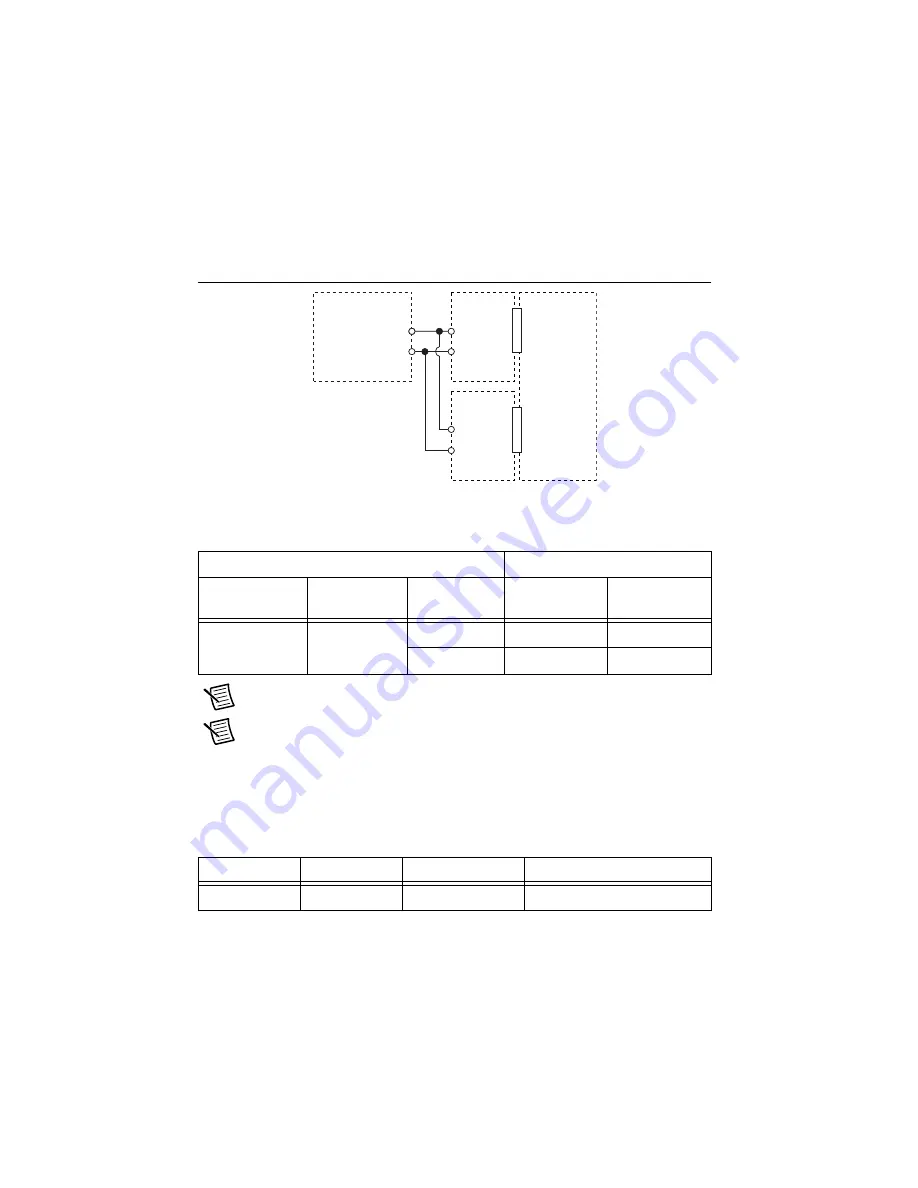
Connect the NI 9218 to the calibrator as shown in Figure 5.

Figure 5.  

Voltage Accuracy Verification Connections

2.

Configure calibrator according to Table 14.

Note

The test limits listed in Table 14 are derived using the values in Table 32.

Note

The uncertainty of the calibration standard is not included in these limits.

3.

Configure the NI 9218 for the NI 9982 measurement adapters using MAX.

4.

Acquire and calculate the AC magnitude.
a.

Create an AI voltage task on the NI 9218 according to Table 15.

Table 14.  

NI 9218 Verification Test Limits for Accuracy

Test Point

2-Year Limits

Signal Type

Frequency 

(kHz)

Amplitude 

(Vrms)

Lower Limit 

(Vrms)

Upper Limit 

(Vrms)

Sine wave

1

1

0.998

1.002

3

2.994

3.006

Table 15.  

NI 9218 Configuration for Phase Matching Verification

Min (V)

Max (V)

Scaled Units

Channel Configuration

-5

5

Volts

AC Coupled

AI+

AI–

NI 99

8

2

C

a

li

b

r

a

tor

+

AI+

AI–

NI 99

8

2

NI 921

8

D

S

UB/LEMO

CH 0

D

S

UB/LEMO

CH 1

Summary of Contents for 9218

Page 1: ...rification 22 mV V mode 14 Adjustment 17 Voltage Accuracy Adjustment 16 V mode 17 Voltage Accuracy Adjustment 60 V mode 18 Voltage Accuracy Adjustment 65 mV mode 19 Current Accuracy Adjustment 20 mA mode 20 Voltage Accuracy Adjustment IEPE 5 V mode 20 Bridge Accuracy Adjustment 22 mV V mode 21 EEPROM Update 23 Reverification 23 Accuracy Under Calibration Conditions 23 Worldwide Support and Service...

Page 2: ...ed Guide NI 9218 connection information NI 9218 Datasheet NI 9218 circuitry and specifications NI DAQmx Readme Operating system and application software support in NI DAQmx LabVIEW Help LabVIEW programming concepts and reference information about NI DAQmx VIs and functions NI DAQmx C Reference Help Reference information for NI DAQmx C functions and NI DAQmx C properties NI DAQmx NET Help Support f...

Page 3: ...llowing specifications 100 ppm gain error 3 µV offset error 3 µV offset at voltages less than 60 mV 200 mV offset at voltages less than 15 V 1 mV offset at voltages less than 60 V 20 mA mode Use a device that can source currents as high as 15 mA 200 ppm gain error and offset error 1 µA IEPE 5 V mode IEPE 5 V mode Use a device that can source 1 kHz 3 Vrms AC sinusoidal signals with amplitude uncert...

Page 4: ... The device temperature will be greater than the ambient temperature Keep relative humidity below 80 Allow a warm up time of at least 10 minutes to ensure that the NI 9218 measurement circuitry is at a stable operating temperature Only one of each NI 9982 NI 9983 and NI 9987 is sufficient for this calibration procedure Discrete Resistors Bridge 22 mV mode Bridge 22 mV mode TCR 25 ppm C Resistor va...

Page 5: ...odule is working properly 9 Ensure that the ambient temperature of your test environment is 23 C 5 C Verification This section provides instructions for verifying the NI 9218 specifications The following performance verification procedures describe the sequence of operations and test points required to verify the NI 9218 and assumes that adequate traceable uncertainties are available for the calib...

Page 6: ... for the NI 9983 measurement adapters using MAX 6 Acquire and average samples a Create an AI current task on the NI 9218 according to Table 2 b Configure the AI current task timing according to Table 3 c Start the task d Average the readings and record the average e Stop and clear the task 7 Set the calibrator to Standby mode STBY Table 2 NI 9218 Configuration for Accuracy Verification Min mA Max ...

Page 7: ...determine the As Found status of the NI 9218 1 Set the calibrator to Standby mode STBY 2 Connect the NI 9218 to the calibrator as shown in Figure 2 Figure 2 Voltage Accuracy Verification Connections 3 Set the calibrator voltage to a Test Point value indicated in Table 7 4 Set the calibrator to Operate mode OPR 5 Configure the NI 9218 for the 9987 measurement adapters using MAX Table 4 NI 9218 Veri...

Page 8: ...ble 7 Note The test limits listed in Table 7 are derived using the values in Table 32 Note The uncertainty of the calibration standard is not included in these limits 10 Disconnect the calibrator from the device Table 5 NI 9218 Configuration for Accuracy Verification Min V Max V Scaled Units Channel Configuration 60 60 Volts DC Coupled Table 6 NI 9218 Timing Configuration Sample Mode Samples Per C...

Page 9: ... the NI 9218 for the 9982 measurement adapters using MAX 6 Acquire and average samples a Create an AI voltage task on the NI 9218 according to Table 8 b Configure the AI voltage task timing according to Table 9 c Start the task d Average the readings and record the averages e Stop and clear the task 7 Set the calibrator to Standby mode STBY Table 8 NI 9218 Configuration for Accuracy Verification M...

Page 10: ...e As Found status of the NI 9218 1 Set the calibrator to Standby mode STBY 2 Connect the NI 9218 to the calibrator as shown in Figure 4 Figure 4 Voltage Accuracy Verification Connections 3 Set the calibrator voltage to a Test Point value indicated in Table 13 4 Set the calibrator to Operate mode OPR 5 Configure the NI 9218 for the NI 9982 measurement adapters using MAX Table 10 NI 9218 Verificatio...

Page 11: ...in Table 13 Note The test limits listed in Table 13 are derived using the values in Table 32 Note The uncertainty of the calibration standard is not included in these limits 10 Disconnect the calibrator from the device Table 11 NI 9218 Configuration for Accuracy Verification Min mV Max mV Scaled Units Channel Configuration 65 65 Volts DC Coupled Table 12 NI 9218 Timing Configuration Sample Mode Sa...

Page 12: ...calibration standard is not included in these limits 3 Configure the NI 9218 for the NI 9982 measurement adapters using MAX 4 Acquire and calculate the AC magnitude a Create an AI voltage task on the NI 9218 according to Table 15 Table 14 NI 9218 Verification Test Limits for Accuracy Test Point 2 Year Limits Signal Type Frequency kHz Amplitude Vrms Lower Limit Vrms Upper Limit Vrms Sine wave 1 1 0...

Page 13: ...fore acquiring samples c Start the task d Calculate and record the AC magnitude for each channel on the NI 9218 NI recommends using the Extract Single Tone Information VI to calculate the magnitude Note The output of the Extract Single Tone Information is in Vpk To convert to RMS use the following equation Vrms Vpk 2 e Disable the calibrator f Stop and clear the task 7 Compare the AC magnitude to ...

Page 14: ...s when connecting the equipment to the NI 9218 Connect the leads of DMM2 as close as possible to the AI and AI terminals on the NI 9982 Connect the leads of DMM1 as close as possible to the RS and RS leads of the NI 9982 Figure 6 Bridge Accuracy Verification Connections Configuration 1 Figure 7 Bridge Accuracy Verification Connections Configuration 2 10 k 249 10 k Va Vb DMM 1 RS RS EX EX AI NI 998...

Page 15: ...2 for a voltage measurement in the 100 mV range 5 Enable autozero on DMM2 6 Configure the NI 9218 for the NI 9982 measurement adapters using MAX Table 17 NI 9218 Verification Test Limits for Accuracy Excitation Value Test Point 2 Year Limits Location Value Lower Limit mV V Upper Limit mV V 2 V Max Configuration 1 0 050 0 050 Mid Configuration 2 0 036 0 036 Min Configuration 3 0 050 0 050 3 3 V Max...

Page 16: ... measurements h Perform the following calculation using the recorded Ratioref and Ratiochannel values Accuracy Ratiochannel Ratioref i Compare the result of step h to the limits in Table 17 j Stop and clear the task 8 Repeat steps 2 through 7 for each test point in Table 17 9 Repeat steps 1 through 8 for each excitation value specified in Table 17 10 Disconnect the DMMs and resistors from the NI 9...

Page 17: ...nfigure the DAQmx Setup 9218 Calibration function according to Table 20 d Call the DAQmx Get 9218 Calibration Adjustment Points function to obtain an array of recommended calibration voltages for the NI 9218 e Set the calibrator to a reference value determined by the array of recommended calibration voltages f Set the calibrator to Operate mode OPR g Call and configure the DAQmx Adjust 9218 Calibr...

Page 18: ...justment Connections 4 Adjust the NI 9218 a Initialize a calibration session on the NI 9218 The default password is NI b Input the external temperature in degrees Celsius using the DAQmx Set Temperature C Series Calibration function c Call and configure the DAQmx Setup 9218 Calibration function according to Table 22 d Set the DMM to the most appropriate range for 390 kΩ resistance measurement e Me...

Page 19: ...unction c Call and configure the DAQmx Setup 9218 Calibration function according to Table 24 d Call the DAQmx Get 9218 Calibration Adjustment Points function to obtain an array of recommended calibration voltages for the NI 9218 e Set the calibrator to a reference value determined by the array of recommended calibration voltages f Set the calibrator to Operate mode OPR g Call and configure the DAQ...

Page 20: ...g to Table 26 d Call and configure the DAQmx 9218 Adjustment Calibration function according to Table 27 e Use the DAQmx Close External Calibration to close and commit the calibration session f Repeat steps c through e for each channel Voltage Accuracy Adjustment IEPE 5 V mode Complete the following procedure to adjust the accuracy performance of the NI 9218 1 Connect the NI 9218 to the calibrator ...

Page 21: ...ray of recommended calibration value h Use the DAQmx Close External Calibration to close and commit the calibration session i Repeat steps c through h for each channel 4 Disconnect the NI 9218 from the calibrator Bridge Accuracy Adjustment 22 mV V mode Complete the following steps to adjust the full bridge accuracy of the NI 9218 1 Connect the NI 9218 and DMMs to the resistor network as shown in F...

Page 22: ...following the diagram in Figure 8 i Acquire voltage measurements with both DMMs Perform the following calculation using the two DMM measurements Note Perform the DMM measurements simultaneously in order to reduce error from drift in the resistors j Call and configure the DAQmx Adjust 9218 Calibration function according to Table 31 Note The NI 9218 acquisition starts each time the adjustment functi...

Page 23: ...ave run verification with another measurement adapter before returning your device to NI Refer to Worldwide Support and Services for assistance in returning the device to NI Accuracy Under Calibration Conditions The values in the following table are based on calibrated scaling coefficients which are stored in the onboard EEPROM The following accuracy table is valid for calibration under the follow...

Page 24: ...DoC is our claim of compliance with the Council of the European Communities using the manufacturer s declaration of conformity This system affords the user protection for electromagnetic compatibility EMC and product safety You can obtain the DoC for your product by visiting ni com certification If your product supports calibration you can obtain the calibration certificate for your product at ni ...

Page 25: ...DSUB Pinout and Pin Assignments 5 4 3 2 1 9 8 7 6 V V 5 4 3 2 1 9 8 7 6 Optional sensor excitation In 65 mV mode you must tie pin 7 AI to pin 3 EX DSUB PINOUT Pin 1 2 3 4 5 6 7 8 9 Full Bridge EX EX RS RS AI AI SC SC 65 mV EX EX AI AI 16 V EX AI EX AI IEPE AI AI TEDS T T PIN ASSIGNMENT BY MODE ...

Page 26: ...on at ni com legal export compliance for the NI global trade compliance policy and how to obtain relevant HTS codes ECCNs and other import export data NI MAKES NO EXPRESS OR IMPLIED WARRANTIES AS TO THE ACCURACY OF THE INFORMATION CONTAINED HEREIN AND SHALL NOT BE LIABLE FOR ANY ERRORS U S Government Customers The data contained in this manual was developed at private expense and is subject to the...

Reviews: