NI 9218 Calibration Procedure
|
© National Instruments
|
15
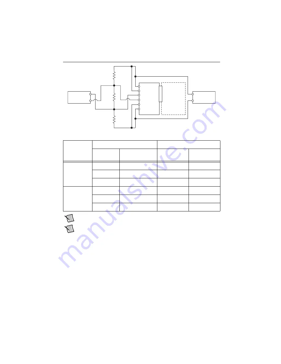
Figure 8.
Bridge Accuracy Verification Connections (Configuration 3)
Note
The test limits listed in Table 17 are derived using the values in Table 32.
Note
The uncertainty of the calibration standard is not included in these limits.
2.
Configure DMM1 for a voltage measurement in the 10 V range.
3.
Enable autozero on DMM1.
4.
Configure DMM2 for a voltage measurement in the 100 mV range.
5.
Enable autozero on DMM2.
6.
Configure the NI 9218 for the NI 9982 measurement adapters using MAX.
Table 17.
NI 9218 Verification Test Limits for Accuracy
Excitation
Value
Test Point
2-Year Limits
Location
Value
Lower Limit
(mV/V)
Upper Limit
(mV/V)
2 V
Max
Configuration 1
-0.050
0.050
Mid
Configuration 2
-0.036
0.036
Min
Configuration 3
-0.050
0.050
3.3 V
Max
Configuration 1
-0.022
0.022
Mid
Configuration 2
-0.007
0.007
Min
Configuration 3
-0.022
0.022
10 k
˖
249
˖
10 k
˖
V
a
V
b
DMM 1
R
S
+
R
S
–
EX+
EX–
AI+
NI 99
8
2
AI–
HI
LO
DMM 2
HI
LO
NI 921
8
D
S
UB/LEMO
CH
x


