© 2015–2016 National Instruments. All rights reserved.
375372B-01
Jul16
Refer to the
NI Trademarks and Logo Guidelines
at
ni.com/trademarks
for more information on NI trademarks. Other product and company
names mentioned herein are trademarks or trade names of their respective companies. For patents covering NI products/technology, refer to the
appropriate location:
Help»Patents
in your software, the
patents.txt
file on your media, or the
National Instruments Patents Notice
at
ni.com/patents
. You can find information about end-user license agreements (EULAs) and third-party legal notices in the readme file for your
NI product. Refer to the
Export Compliance Information
at
ni.com/legal/export-compliance
for the NI global trade compliance policy
and how to obtain relevant HTS codes, ECCNs, and other import/export data. NI MAKES NO EXPRESS OR IMPLIED WARRANTIES AS TO THE
ACCURACY OF THE INFORMATION CONTAINED HEREIN AND SHALL NOT BE LIABLE FOR ANY ERRORS. U.S. Government Customers: The data
contained in this manual was developed at private expense and is subject to the applicable limited rights and restricted data rights as set forth in
FAR 52.227-14, DFAR 252.227-7014, and DFAR 252.227-7015.
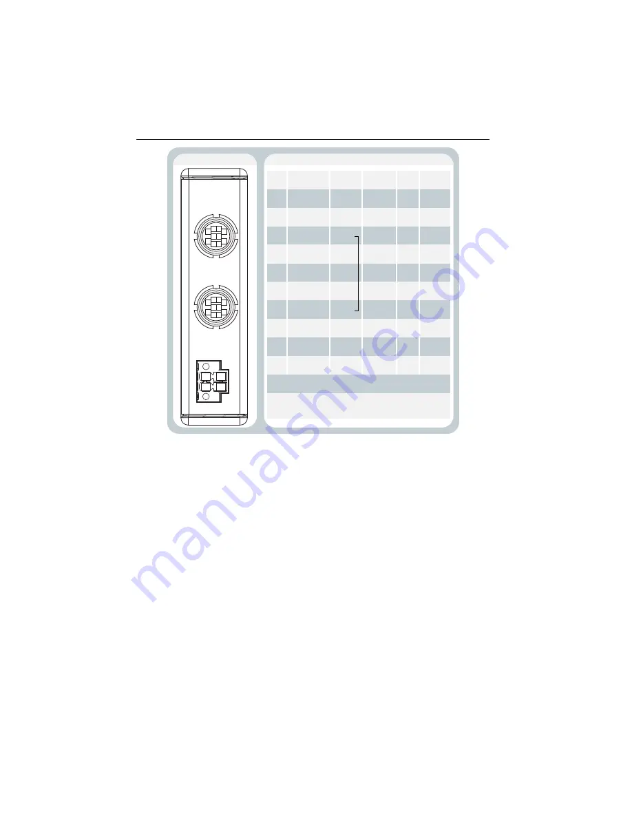
Figure 11.
NI 9218 with LEMO Pinout and Pin Assignments
4
5
1
8
3
2
10 9
6 7
V+
V–
V+
V–
4
5
1
8
3
2
10 9
6 7
LEMO PINOUT
*
Option
a
l
s
en
s
or excit
a
tion.
†
In ±65 mV mode, yo
u
m
us
t tie pin 7 (AI–) to
pin
3
(EX–).
PIN ASSIGNMENT BY MODE
Pin
1
2
3
4
5
6
7
8
9
10
Full-Brid
g
e
EX+
—
EX–
R
S
+
R
S
–
AI+
AI–
S
C
S
C
—
±65 mV
EX+
*
—
EX–
*
—
—
AI+
AI–
†
—
—
—
—
±16 V
IEPE
—
AI+
AI–
—
—
—
—
—
—
TED
S
—
T1+
T2+
T1–, T2–
—
—
—
—
—
—
—
—
EX+
*
AI–, EX–
*
—
—
AI+
—
—
—


