background image

NI 9505E Operating Instructions and Specifications

18

ni.com

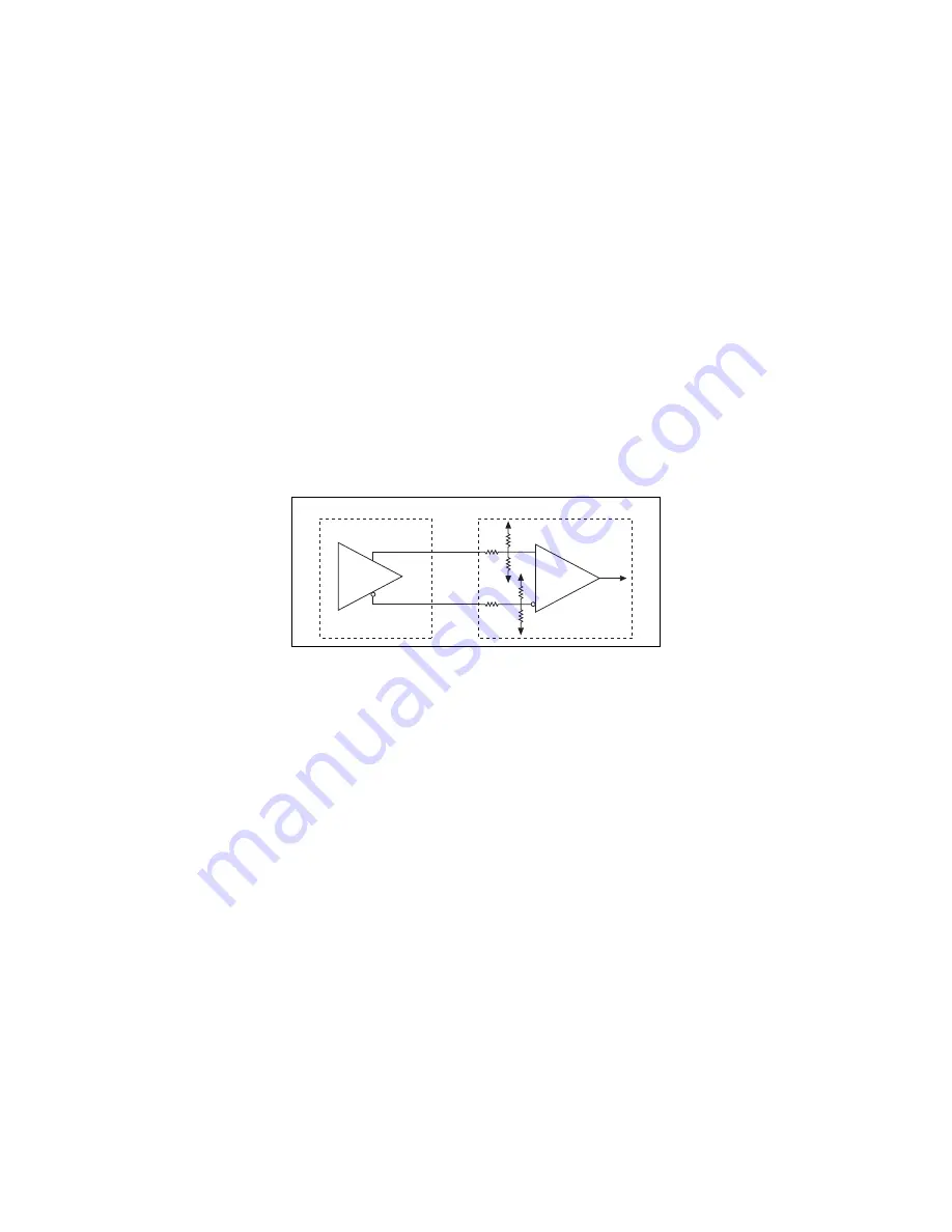
If the encoder cable length is greater than 3.05 m (10 ft), use 
encoders with differential line driver outputs for your applications. 
Power for a +5 V encoder—generated by a power supply on the 
NI 9505E—is available on pin 5 of the DSUB connector.

Figure 8.  

Differential Encoder Input Circuit

Receiver 

Phase +

Phase –

Encoder 

COM

COM

+5 V

+5 V

Encoder

NI 9505E

Summary of Contents for 9505E

Page 1: ...OPERATING INSTRUCTIONS AND SPECIFICATIONS NI 9505E DC Brushed Servo Drive ...

Page 2: ...you are using For information about installing configuring and programming the system refer to the system documentation Visit ni com info and enter cseriesdoc for information about C Series documentation Caution National Instruments makes no electromagnetic compatibility EMC or CE marking compliance claims for the NI 9505E The end product supplier is responsible for conformity to any and all compl...

Page 3: ...9505E Operating Instructions and Specifications NI 9505E Dimensions The following figure shows the dimensions of the NI 9505E Figure 1 NI 9505E Dimensions in Millimeters Inches 73 4 2 89 0 0 0 00 0 0 0 00 26 7 1 05 58 4 2 30 66 0 2 60 ...

Page 4: ...LabVIEW FPGA Module A typical application contains a position loop velocity loop and current loop implemented in the LabVIEW FPGA Module block diagram Depending on the application you may not need to use all three loops The examples installed in the labview examples CompactRIO Module Specific NI 9505 directory illustrate methods for implementing each of these loops The NI 9505E returns the motor o...

Page 5: ...NI 9505E and are processed in the LabVIEW FPGA Module for use in the position and velocity loops Refer to Figure 5 for a typical NI 9505E connection example including encoder and E Stop inputs For more advanced motion control applications NI SoftMotion provides functions for trajectory generation spline interpolation position and velocity PID control and encoder implementation using both the LabVI...

Page 6: ...t Loop Fault Monitor Bridge Controller Fault Detection H Bridge Current Sense Encoder Feedback DC Servo Motor Velocity Command Current Command Position Setpoint LabVIEW FPGA Module NI 9505E Motor PWM Encoder Feedback Position Decoder Current Feedback Velocity Feedback Position Feedback Velocity Estimator Proportional to Torque ...

Page 7: ...tions and Specifications Figure 3 LabVIEW FPGA Module NI 9505E PID Loop Position Setpoint Position Error Velocity Acceleration Vff Kp Ki Kd Kv Current Command Proportional to Torque Position Decoder LabVIEW FPGA Module Encoder Feedback Aff Position Feedback ...

Page 8: ... method in software Refer to the NI 9505 Reference Help book in the LabVIEW Help available by selecting Help Search the LabVIEW Help for more information about enabling the drive When the NI 9505E is removed from the chassis while it is enabled the power to the motor is removed and the motor decelerates to a stop based on its own friction Current Error Motor PWM Kp Ki Current Limiter Current Comma...

Page 9: ...NI 9505E has four LEDs to display status information Power The Power LED green illuminates when the NI 9505E is properly inserted into a powered chassis Note The Power LED does not illuminate when the chassis is in sleep mode 1 Power green 2 VSUP Motor Power green 3 Disable yellow 4 Fault red 1 2 3 4 ...

Page 10: ...e using the Enable Drive method in software Refer to the NI 9505 Reference Help book in the LabVIEW Help available by selecting Help Search the LabVIEW Help for more information about this method Fault Caution If the Fault LED is lit determine the cause of the fault and correct it before enabling the drive The Fault LED red illuminates when a fault occurs A fault disables the drive Causes for faul...

Page 11: ...ts Refer to the Specifications section for more information about PWM Sleep Mode This module supports a low power sleep mode Support for sleep mode at the system level depends on the chassis that the module is plugged into Refer to the chassis manual for information about support for sleep mode If the chassis supports sleep mode refer to the software help for information about enabling sleep mode ...

Page 12: ...ergency stop input and a connection to COM Refer to Table 1 for the pin assignments The NI 9505E also has a screw terminal connector that provides connections to a motor DC power supply and a DC brushed servo motor Connect the positive lead of the power supply to terminal 4 VSUP and the negative lead to terminal 3 COM Refer to Table 2 for the terminal assignments Note You must use 2 wire ferrules ...

Page 13: ...der Phase A 2 Encoder Phase B 3 Encoder Index Phase Z 4 Emergency Stop E Stop 5 5 V output 6 Encoder Phase A 7 Encoder Phase B 8 Encoder Index Phase Z 9 Common COM Table 2 NI 9505E Screw Terminal Terminal Assignments Module Terminal Signal M MOTOR M MOTOR C COM motor DC power supply reference V VSUP motor DC power supply 9 8 7 6 5 4 3 2 1 M M C V ...

Page 14: ... com Figure 5 shows a typical NI 9505E connection example including encoder and E Stop inputs Figure 5 NI 9505E Connections Motor M M VSUP COM Motor DC Power Supply NI 9505E Shield Shield Phase A Phase B Index 5 V COM Shield 24 V E Stop Encoder Feedback COM ...

Page 15: ...erminal connector to increase the output power of the module at temperatures below 85 ºC The NI 9931 is available from ni com NI part number 780571 01 or by calling your National Instruments sales representative Refer to the Specifications section for more information Refer to Figure 6 for an illustration Figure 6 NI 9505E Module with Optional Screw Terminal Accessory MOTOR MOTOR COM Vsup ...

Page 16: ...Motor direction is as follows Forward Clockwise CW facing motor shaft Reverse Counterclockwise CCW facing motor shaft Figure 7 shows clockwise and counterclockwise motor rotation Figure 7 Clockwise and Counterclockwise Motor Rotation Tip If the motor does not turn in the desired direction reverse the MOTOR and MOTOR signals CCW CW ...

Page 17: ...ers by using a 1 kΩ pull up resistor on each line to 5 VDC Refer to the Specifications section for more information about the encoder inputs The encoder signals are raw digital input signals These signals are used in the LabVIEW FPGA Module for position and or velocity feedback Figures 2 and 3 illustrate the use of the encoder signals in a position and velocity loop in the LabVIEW FPGA Module Refe...

Page 18: ...n 3 05 m 10 ft use encoders with differential line driver outputs for your applications Power for a 5 V encoder generated by a power supply on the NI 9505E is available on pin 5 of the DSUB connector Figure 8 Differential Encoder Input Circuit Receiver Phase Phase Encoder COM COM 5 V 5 V Encoder NI 9505E ...

Page 19: ...One industry standard directional polarity is as follows Positive forward clockwise CW facing motor shaft Negative reverse counterclockwise CCW facing motor shaft Refer to Figure 7 for a depiction of clockwise and counterclockwise rotation If encoder counting does not behave as expected change the encoder polarity in the FPGA or swap the Phase A and Phase B connections Receiver Encoder Signal Enco...

Page 20: ... operation Emergency Stop Signal The E Stop signal is an input to the drive from an emergency stop switch Figure 10 shows a simplified schematic of the emergency stop input circuit When the emergency stop switch is closed current flows through the circuit and the drive is enabled When an external event activates the emergency stop switch the switch opens and current stops flowing disabling the dri...

Page 21: ...se the following guidelines when selecting cables for the NI 9505E Use shielded cables with a low impedance connection to chassis ground to minimize noise and signal crosstalk Tie the VSUP cable shield to chassis ground at the module side only Tie the motor cable shield to chassis ground at the motor side only Optocoupler COM 24 V E Stop 3 3 V NI 9505E E Stop ...

Page 22: ...o reduce high frequency noise Add clamp on ferrites to cables to further reduce emissions Add a balun to the power cable to attenuate conducted and radiated emissions Using the NI 9505E with Other C Series Modules Due to additional ambient heating of the NI 9505E when supplying more than 1 A to the load the room temperature 25 ºC 5 ºC specifications of adjacent modules are not valid The full opera...

Page 23: ... All voltages are relative to COM unless otherwise noted Operating Conditions Motor DC power supply VSUP 8 to 30 VDC 12 A max Motor continuous current1 Motor 1 A 85 ºC 5 A 40 ºC With NI 9931 screw terminal accessory 1 A 85 ºC 7 3 A 40 ºC Peak current2 12 A 2 s max 1 For more information about maximum continuous current at temperatures less than 85 ºC visit ni com info and enter rdmot2 2 Allow at l...

Page 24: ...ulse width will result in unpredictable performance Minimum pulse width high or low 2 μs Drive direction update rate Nominally 20 μs Current loop ADC resolution 12 bits Current range 12 7 A Maximum update rate 20 μs Minimum inductance 500 μH MTBF 821 178 hours at 25 ºC Bellcore Issue 2 Method 1 Case 3 Limited Part Stress Method ...

Page 25: ...Drive Protection Undervoltage 6 V Caution VSUP greater than 40 V will result in damage to the module Overvoltage 32 V Reverse polarity 30 V Motor terminal MOTOR short to ground Yes Motor terminal MOTOR short to VSUP Yes Temperature fault trip point 115 ºC module temperature Encoder Input Characteristics Number of inputs 3 Input type Differential or single ended Voltage range 0 to 5 5 VDC ...

Page 26: ...reshold 2 4 V Input low threshold 0 8 V Differential Input threshold 700 mV line driver compatible Common mode voltage 7 to 12 V Input current 1 mA Maximum quadrature frequency 5 MHz E Stop Input Input voltage range 0 to 30 V Input ON voltage 3 5 to 30 V Input OFF voltage 0 to 2 V Turn on current 500 μA typical 1 mA maximum ...

Page 27: ...1 5 W max Sleep mode 0 4 mW max Encoder Power Supply 5 V regulated output Voltage tolerance 5 V 5 VSUP 8 V Current 125 mA Physical Characteristics Use a dry low velocity stream of air to clean the module If needed use a soft bristle brush for cleaning around components Note Fortwo dimensionaldrawingsandthree dimensional models of the C Series module and connectors visit ni com dimensions and searc...

Page 28: ...que for screw terminals 0 5 to 0 6 N m 4 4 to 5 3 lb in Ferrules 0 25 mm2 to 2 5 mm2 Weight without screw terminal 47 g 1 7 oz NI 9931 Screw Terminal Accessory Screw terminal wiring 14 to 26 AWG copper conductor wire with 7 mm 0 28 in of insulation stripped from the end Torque for screw terminals 0 5 to 0 6 N m 4 4 to 5 3 lb in Ferrules 0 25 mm2 to 1 5 mm2 Weight 40 g 1 4 oz ...

Page 29: ...tand 750 Vrms verified by a 5 s dielectric withstand test Measurement Category I is for measurements performed on circuits not directly connected to the electrical distribution system referred to as MAINS voltage MAINS is a hazardous live electrical supply system that powers equipment This category is for measurements of voltages from specially protected secondary circuits Such voltage measurement...

Page 30: ... 61010 1 CSA 61010 1 Note For UL and other safety certifications refer to the product label or the Online Product Certification section Online Product Certification Refer to the product Declaration of Conformity DoC for additional regulatory compliance information To obtain product certifications and the DoC for this product visit ni com certification search by module number or product line and cl...

Page 31: ...IEC 60068 2 1 IEC 60068 2 2 40 to 85 C Operating humidity IEC 60068 2 56 10 to 90 RH noncondensing Storage humidity IEC 60068 2 56 5 to 95 RH noncondensing Maximum altitude 2 000 m Pollution Degree 2 Environmental Management National Instruments is committed to designing and manufacturing products in an environmentally responsible manner NI recognizes that eliminating certain hazardous substances ...

Page 32: ...d in this document Waste Electrical and Electronic Equipment WEEE EU Customers At the end of their life cycle all products must be sent to a WEEE recycling center For more information about WEEE recycling centers and National Instruments WEEE initiatives visit ni com environment weee ᄤֵᙃѻક ᶧ ࠊㅵ ࡲ Ё RoHS Ё ᅶ National Instruments ヺড়Ё ᄤֵᙃ ѻકЁ䰤ࠊՓ ᶤѯ ᆇ 䋼ᣛҸ RoHS DŽ Ѣ National Instruments Ё RoHS ড়㾘ᗻֵᙃˈ䇋ⱏᔩ...

Page 33: ... 3504 National Instruments also has offices located around the world to help address your support needs For telephone support in the United States create your service request at ni com support and follow the calling instructions or dial 512 795 8248 For telephone support outside the United States contact your local branch office Australia 1800 300 800 Austria 43 662 457990 0 Belgium 32 0 2 757 002...

Page 34: ...fer to the appropriate location Help Patents in your software the patents txt file on your media or the National Instruments Patent Notice at ni com patents Korea 82 02 3451 3400 Lebanon 961 0 1 33 28 28 Malaysia 1800 887710 Mexico 01 800 010 0793 Netherlands 31 0 348 433 466 New Zealand 0800 553 322 Norway 47 0 66 90 76 60 Poland 48 22 328 90 10 Portugal 351 210 311 210 Russia 7 495 783 6851 Sing...

Reviews: