© National Instruments
|
4-3
ATE Core Configurations RMX-10011 User Manual
USB Ports
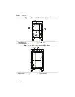
The Power Entry Panel has two USB ports which provide access to extension cables within the
rack. These cables can be connected to provide external access to USB ports on internal equipment.
Ethernet Port
The Power Entry Panel has an Ethernet port connected to a switch inside the rack to facilitate
network connectivity to internal equipment. Refer to Figure 1-5,
for more details about the Ethernet Switch location.
Connecting to a Network
Complete the following steps to connect the ATE to a network.
1.
Connect an active network cable to the Ethernet port on the Power Entry Panel
2.
Configure the network and user settings according to the standard practices of your facility
and within the IP address setting restrictions.
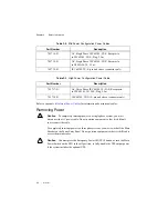
Removing Power
Caution
To completely interrupt power to a single phase system, you
must
disconnect the AC power cable. Do not position equipment so that it is difficult
to disconnect the cable.
To completely interrupt power to a three phase system, you
must
switch off the main
breaker on the Power Entry Panel. Do
not
position equipment so that it is difficult to
access the main breaker. Do
not
proceed unless qualified personnel has reviewed all
installation instructions, written warnings and cautions.
Caution
You
must
press the Emergency Power Off (EPO) button, or turn the Main
Power Switch on the EPO to the off position, to fully disable the UPS output power
if the system includes the optional UPS.
Power Distribution Unit (PDU)
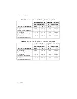
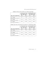
A PDU takes an input power signal and distributes it to a number of outlets that can power
components of the system. These internal power outlets from the PDU have a rated voltage
and current and are available for both alternating and direct current.
•
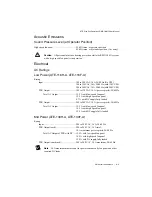
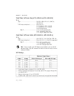
Low Power ATE Core Configuration systems utilize a single-phase PDU that supports
global voltages (100-240 V, 50-60 Hz) and has a 20 A (IEC C19) input connector which
cables directly to the Power Entry Panel.
•
Mid Power ATE Core Configuration systems support double the total system power of the
low-power systems. Mid Power systems utilize two of the single-phase PDUs with the
exception that the second PDU does not provide DC outputs. Both PDUs wire directly
to the Power Entry Panel.

