background image

© National Instruments

|

B-1

B

Internal Power Cables

This appendix lists the internal power cables for the ATE Core Configurations.

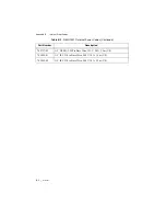
Table B-1.  

RMX-10011 Internal Power Cables

Part Number

Description

785707-01

AC, IEC C20 to NEMA 5-20R, 125 V, 16 A, 0.25 m (US)

785708-01

AC, IEC C19 to NEMA 5-20P, 125 V, 16 A, 2.5 m (US)

785709-01

AC, IEC C20 to IEC C13, 240 V, 10 A (EU), 16 A (UL), 1.5 m (US, EU)

785709-02

AC, IEC C20 to IEC C13, 240 V, 10 A (EU), 16 A (UL), 2.5 m (US, EU)

785710-01

AC, IEC C20 to IEC C19, 240 V, 16 A, 1.5 m (US, EU, China, Korea)

785710-0112

AC, IEC C20 to IEC C19, 240 V, 16 A, 1.5 m (Japan)

785710-02

AC, IEC C20 to IEC C19, 240 V, 16 A, 2.5 m (US, EU, China, Korea)

785710-0212

AC, IEC C20 to IEC C19, 240 V, 16 A, 2.5 m (Japan)

785711-01

AC, IEC C20 to Bare Wire, 240 V, 16 A, 1.5 m (US, EU, China, Korea)

785711-0112

AC, IEC C20 to Bare Wire, 240 V, 16 A, 1.5 m (Japan)

785711-02

AC, IEC C20 to Bare Wire, 240 V, 16 A, 2.5 m (US, EU, China, Korea)

785711-0212

AC, IEC C20 to Bare Wire, 240 V, 16 A, 2.5 m (Japan)

785712-01

AC, IEC C14 to Bare Wire, 240 V, 10 A, 1.5 m (EU, China, Korea)

785712-02

AC, IEC C14 to Bare Wire, 240 V, 10 A, 2.5 m (EU, China, Korea)

785713-01

AC, IEC C14 to IEC C13, 240 V, 10 A, 1.5 m (US)

785713-0112

AC, IEC C14 to IEC C13, 240 V, 10 A, 1.5 m (Japan)

785713-02

AC, IEC C14 to IEC C13, 240 V, 10 A, 2.5 m (US)

785713-0401

AC, IEC C14 to IEC C13, 240V, 10 A, 1.5 m (EU, China, Korea)

785713-0402

AC, IEC C14 to IEC C13, 240V, 10 A, 2.5 m (EU, China, Korea)

785727-01

AC, NEMA 5-20P to Bare Wire, 125 V, 20 A, 1.5m (US)

Summary of Contents for ATE Core Configurations

Page 1: ...ATE Core Configurations RMX 10011 User Manual ATE Core Configurations RMX 10011 User Manual October 2017 377138A 01 ...

Page 2: ...bers email addresses and current events National Instruments Corporate Headquarters 11500 North Mopac Expressway Austin Texas 78759 3504 USA Tel 512 683 0100 For further support information refer to the NI Services appendix To comment on National Instruments documentation refer to the National Instruments web site at ni com info and enter the Info Code feedback 2017 National Instruments All rights...

Page 3: ...ESS FOR A PARTICULAR PURPOSE TITLE OR NON INFRINGEMENT AND ANY WARRANTIES THAT MAY ARISE FROM USAGE OF TRADE OR COURSE OF DEALING NI DOES NOT WARRANT GUARANTEE OR MAKE ANY REPRESENTATIONS REGARDING THE USE OF OR THE RESULTS OF THE USE OF THE PRODUCTS IN TERMS OF CORRECTNESS ACCURACY RELIABILITY OR OTHERWISE NI DOES NOT WARRANT THAT THE OPERATION OF THE PRODUCTS WILL BE UNINTERRUPTED OR ERROR FREE ...

Page 4: ...ies independent from National Instruments and have no agency partnership or joint venture relationship with National Instruments Patents For patents covering National Instruments products technology refer to the appropriate location Help Patents in your software the patents txt file on your media or the National Instruments Patent Notice at ni com patents Export Compliance Information Refer to the...

Page 5: ...re encouraged to try to correct the interference by one or more of the following measures Reorient the antenna of the receiver the device suffering interference Relocate the transmitter the device generating interference with respect to the receiver Plug the transmitter into a different outlet so that the transmitter and the receiver are on different branch circuits Some hardware may require the u...

Page 6: ...ts 2 6 Power Connection 2 6 Power Recommendations 2 6 Cooling Requirements 2 7 Exhaust 2 7 Chapter 3 Safety Information Safety Requirements 3 1 AC Mains Cables 3 1 Removing Power 3 2 Operator Safety Information 3 3 Safety Features 3 3 Safety Shutoff Thermostats 3 3 Emergency Power Off EPO Panel 3 4 EPO Temperature Controller 3 4 Circuit Protection 3 4 Walls and Rear Door 3 4 Grounding 3 4 Chapter ...

Page 7: ...ain Power Switch 4 4 Temperature Controller 4 4 Uninterruptable Power Supply UPS 4 4 System Block Diagrams 4 5 Power States 4 6 Powering On 4 7 Chapter 5 Maintenance Cleaning 5 1 Cleaning the Exterior 5 1 Cleaning Air Intake Filters 5 2 Replacement Parts 5 2 Calibration 5 3 Appendix A Specifications Appendix B Internal Power Cables Appendix C NI Services Glossary Index ...

Page 8: ...nents to simplify design and documentation along with the flexibility for NI and third party instrumentation layout and are meant to be customized for a specific application Nomenclature The ATE Core Configurations are uniquely identified by the voltage and power input type of the system Refer to Appendix A Specifications for more details about ATE Core Configurations power input ratings The follo...

Page 9: ...es show the locations of the ATE Core Configurations hardware Note The following figures show a 24 U Low Power configuration Figure 1 2 Front and Side View of ATE Core Configurations 1 Industrial Casters 2 Side Panel 3 Emergency Power Off EPO Panel 4 Mounting Rails 3 2 4 1 ...

Page 10: ...ATE Core Configurations RMX 10011 User Manual Figure 1 3 Rear and Side View of ATE Core Configurations 1 4U Air Inlet Panel 2 3U Power Entry Panel 3 1U Brush Cable Entry 4 Removable Rear Door 5 Fan Panel 6 Side Panel 1 2 3 4 5 6 ...

Page 11: ...ntroduction Figure 1 4 Side View of ATE Core Configurations Figure 1 5 Cutaway View of Ethernet Switch Location 1 Cable Management 2 Power Distribution Unit 3 Mounting Rails 1 Ethernet Switch 2 Cable Management 1 2 3 3 3 1 2 ...

Page 12: ...esholds Carefully inspect the shipping crate and the rack for damage Check for visible damage to the metal work If damage appears to have been caused during shipment file a claim with the carrier Retain the packing material for possible inspection and or reshipment Figure 2 1 Rack Packaging Assembly 1 Ramp Assembly 2 Removable Block 3 Top Panel 4 Side Panel x2 5 Clamp 6 Bolt Assembly x8 7 Base Ass...

Page 13: ...2 2 ni com Chapter 2 Installation and Configuration Crate Dimensions Figure 2 2 24U Crate Dimensions 673 26 5 1545 60 81 1403 55 25 Ramp 908 35 75 991 39 1031 40 56 Dimensions are in millimeters inches ...

Page 14: ...special tools Ensure that you have the following standard tools to bring up maintain and troubleshoot Screwdrivers Standard Head Large size for side panels and uncrating Small size for PDU DC connectors Phillips Head 1 and 2 1 2 in wrench or socket for uncrating 991 39 1031 40 56 673 26 5 908 35 75 2115 83 25 Ramp 2256 88 81 Dimensions are in millimeters inches ...

Page 15: ...ters for easymovement throughout the facility Duetoweightdistributionoftheinstrumentation thesystemismoststableduringmovementwhen you push from the front or back of the rack Avoid side to side movement except for final positioning Caution Deploying the rack from the shipping crate requires moving it in a back to front direction Never stand directly in front of the rack when loading or unloading fr...

Page 16: ...ipped in separate crates or boxes Use caution to ensure stability while moving your system and prior to assembly of the configured system Caution If you remove equipment from the rack it may no longer be compliant with IEC 61010 1 stability standards Ensure that any modifications you make to the rack configuration maintain sufficient stability in accordance with IEC 61010 1 Any modifications made ...

Page 17: ...cal codes and requirements Wired by a qualified electrician Power Recommendations National Instruments recommends the following requirements Provide separate AC branch for the system due to the current requirements of the system Copper wire for the system drop between the AC source and system Before servicing the ATE Core Configurations physically remove the Mains plug from the power outlet A mini...

Page 18: ... configuration also includes a 4U vent below the rear door to facilitate airflow into the rack Air filters are provided and it is recommended they be properly maintained based on environmental conditions These filters are user serviceable and replacement kits are available on ni com Note Do not block the top exhaust vent or air intake NI recommends maintaining 2U of open space directly above and b...

Page 19: ...cturer may reduce or eliminate equipment and or personnel safety measures Caution Where this symbol is used documentation must be consulted Before connecting the system to a power source read this section and verify that you have complied with all safety requirements and specifications Caution Before undertaking any bring up troubleshooting maintenance or exploratory procedure carefully read the f...

Page 20: ... breaker Caution Y ou must press the Emergency Power Off EPO button or turn the Main Power Switch on the EPO to the off position to fully disable the UPS output power if the system includes the optional UPS Table 3 2 Mid Power Configuration Power Cables Part Number Description 785718 01 AC Single Phase IEC 60309 2P E Receptacle to IEC 60309 2P E Plug 2 5 m 785719 01 AC Single Phase IEC 60309 2P E ...

Page 21: ...system off in the event the rack is unable to provide adequate cooling preventing a safety hazard to the user When triggered by a severe over temperature event the thermostats will shut down the system by cutting power at the Power Entry Panel AC outlet s immediately shutting off power to any downstream equipment including the PDUs Caution Once the thermostats have tripped any touchable or accessi...

Page 22: ...roller The secondary temperature controller on the EPO panel is user configurable and can be used to control the operation of the system for thermal performance but is not a safety temperature protective device Circuit Protection Several layers of circuit protection are designed into the systems The Power Entry Panel has circuit protection to ensure the overall system does not draw current beyond ...

Page 23: ...re are four distinct power configurations available with the ATE Core Configurations Low Power Mid Power High Power Delta High Power Wye Each Power Entry Panel contains Applicable IEC power entry connector Low Power IEC 60320 C20 Mid Power IEC 60309 2P E High Power Delta and Wye IEC 60309 3P N E Applicable circuit protection Applicable line filter for EMI protection within the system Applicable ki...

Page 24: ...ontrols whether AC power will be allowed into the rack If the Main Breaker is off the rack cannot be powered on The Mid Power Power Entry Panel has two additional circuit breakers controlling power output from the Power Entry Panel individually to each Power Distribution Unit in the system 1 Power Inlet Connector 2 Main Breaker 3 Ethernet Port 4 USB Ports 5 Individual Outlet Breakers Mid Power Onl...

Page 25: ...y interrupt power to a three phase system you must switch off the main breaker on the Power Entry Panel Do not position equipment so that it is difficult to access the main breaker Do not proceed unless qualified personnel has reviewed all installation instructions written warnings and cautions Caution Y ou must press the Emergency Power Off EPO button or turn the Main Power Switch on the EPO to t...

Page 26: ...ontrol whether the system is powered If the EPO button is pressed power will not flow past the PEP or optional UPS To release the EPO button once it has been pressed rotate it clockwise Main Power Switch The Main Power Switch is the primary way of controlling whether the system is active It toggles between two positions Standby and On Temperature Controller The Temperature Controller AutomationDir...

Page 27: ...installed Figure 4 5 Mid Power System Block Diagram Safety Shutoff Thermostats Power Entry Panel PEP Emergency Power Off EPO Panel Rack Fans Power Distribution Unit PDU Uninterruptable Power Supply UPS Optional Emergency Power Off EPO Panel Safety Shutoff Thermostats Power Distribution Unit PDU Uninterruptable Power Supply UPS Optional Power Entry Panel PEP Power Distribution Unit PDU Rack Fans ...

Page 28: ...ed Main Power Switch on EPO Panel is off Temperature controller on the EPO Panel is reading a higher temperature than the programmed shutoff value Safety shutoff thermostats have detected an unsafe air exit temperature On A change to this state begins the main power on sequence of the test system All PDUs receive AC power and enable outlets to other system equipment Emergency Power Off EPO The EPO...

Page 29: ... Connector on the Power Entry Panel is connected to AC Mains 2 Verify that the Main Breaker and individual outlet breakers on Mid Power Panel on the back of the Power Entry Panel is in the ON position 3 Confirm that the Emergency Power Off EPO button is not depressed 4 Verify that the programmed temperature shutoff value of the temperature controller located on the EPO Panel is above the current t...

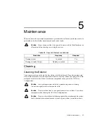
Page 30: ...Remove any soap residue by wiping with a cloth moistened with clear water Do not use abrasive compounds on any part of the ATE Core Configurations Caution Avoid getting moisture inside the system during exterior cleaning Use only enough moisture to dampen the cloth Caution Do not wash the front or rear panel connectors or switches Cover these components while cleaning the ATE Core Configurations C...

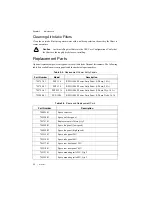
Page 31: ...anels Part Number Model Description 785797 01 PEP 116 RMX 10040 Power Entry Panel 1 Phase 16 A 785798 01 PEP 130 RMX 10040 Power Entry Panel 1 Phase 24 A 785799 01 PEP 3W16 RMX 10040 Power Entry Panel 3 Phase Wye 16 A 785800 01 PEP 3D16 RMX 10040 Power Entry Panel 3 Phase Delta 16 A Table 5 3 Spare and Replacement Parts Part Number Description 784839 01 Spare caster set 785520 01 Spare air filter ...

Page 32: ...ntative or by contacting the designated support resources 785523 01 Spare cable manager 24U 785524 01 Spare cable manager 40U 785512 01 1U filler panels for 19 in rack Qty 5 785513 01 3U filler panels for 19 in rack Qty 3 Table 5 4 Component Repair and Calibration for ATE Core Configurations Component Required Optional Serviceable Calibration Required Rack Required No No Rack Panels Optional No No...

Page 33: ...ched to rack 24U 40U rack 1 000 lb 453 5 kg evenly distributed across each caster Keyboard shelf optional 30 lb 13 6 kg Storage drawer optional 30 lb 13 6 kg The outlet circuit breaker s on the power entry panels PEP 116 and PEP 130 for Low and Mid power ATE Core Configurations are rated for an impact energy level of IK06 1J when tested with a direct vertical impact per IEC 61010 1 3rd Ed Table 15...

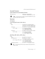
Page 34: ...rating Environment Ambient temperature is defined as the temperature that exists just outside of the air intake on the bottom rear of the rack This temperature may be higher than ambient room temperature depending on the surrounding equipment and or blockages present You must ensure that this ambient temperature does not exceed the rated ambient temperature range Ambient temperature range 5 C to 4...

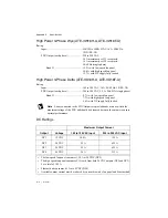
Page 35: ...to 120 VAC 10 A per receptacle 50 60 Hz Total AC Output 15 2 A with low speed fan panel 12 9 A with high speed fan panel 8 7 A with DC supply fully loaded PDU Output 200 to 240 VAC 10 A per receptacle 50 60 Hz Total AC Output 15 5 A with low speed fan panel 14 5 A with high speed fan panel 12 4 A with DC supply fully loaded Mid Power ATE 130H A ATE 130F A Rating Input 200 to 240 VAC 24 A 50 60 Hz ...

Page 36: ...8 7 A with low speed fan panel 7 7 A with high speed fan panel 5 6 A with DC supply fully loaded Note Loads connected to the PDU Output receptacles banks must be within the maximum ratings of the PDU and should be balanced between the outputs to ensure optimal performance DC Ratings Maximum Output Current Output Voltage 100 to 120 VAC Input 200 to 240 VAC Input DC1 12 VDC 10 4 A 12 5 A DC2 24 VDC ...

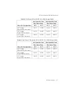
Page 37: ...nd the end use ambient environment the system will be installed in Please refer to following examples for guidelines on using the tables Example 1 A mid power rack will be used in a typical manufacturing environment 28 C ambient with a low speed fan panel and the rack configuration will include equipment that has operational ambient temperature ratings up to 45 C The maximum power that can be diss...

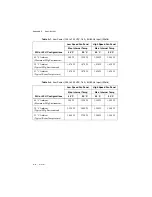
Page 38: ...l Mfg Environment 1 870 W 1 870 W 1 620 W 1 620 W 23 C Ambient Typical Room Temperature 1 870 W 1 870 W 1 620 W 1 620 W Table A 2 Low Power 200 to 240 VAC 16 A 50 60 Hz Input Watts 24U or 40 U Configurations Low Speed Fan Panel High Speed Fan Panel Max Internal Temp Max Internal Temp 45 C 50 C 45 C 50 C 40 C Ambient Maximum Mfg Environment 500 W 1 350 W 1 500 W 1 500 W 28 C Ambient Typical Mfg Env...

Page 39: ...ent Typical Mfg Environment 2 550 W 3 400 W 5 460 W 5 460 W 23 C Ambient Typical Room Temperature 3 400 W 4 300 W 5 460 W 5 460 W Table A 4 High Power 3 Phase Delta 200 to 208 VAC 16 A 50 60 Hz Input Watts 24U or 40 U Configurations Low Speed Fan Panel High Speed Fan Panel Max Internal Temp Max Internal Temp 45 C 50 C 45 C 50 C 40 C Ambient Maximum Mfg Environment 500 W 1 350 W 1 500 W 1 500 W 28 ...

Page 40: ... control and laboratory use EN 61326 1 IEC 61326 1 Class A emissions Basic immunity EN 55011 CISPR 11 Group 1 Class A emissions EN 55022 CISPR 22 Class A emissions EN 55024 CISPR 24 Immunity AS NZS CISPR 11 Group 1 Class A emissions AS NZS CISPR 22 Class A emissions FCC 47 CFR Part 15B Class A emissions ICES 001 Class A emissions Table A 5 High Power 3 Phase Wye 220 380 to 240 415 VAC 16 A 50 60 H...

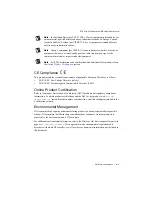
Page 41: ...ctives as follows 2014 35 EC Low Voltage Directive safety 2014 30 EU Electromagnetic Compatibility Directive EMC Online Product Certification Refer to the product Declaration of Conformity DoC for additional regulatory compliance information To obtain product certifications and the DoC for this product visit ni com certification search by model number or product line and click the appropriate link...

Page 42: ...ion about WEEE recycling centers National Instruments WEEE initiatives and compliance with WEEE Directive 2002 96 EC on Waste and Electronic Equipment visit ni com environment weee ᄤֵᙃѻક ᶧ ࠊㅵ ࡲ Ё RoHS Ё ᅶ National Instruments ヺড়Ё ᄤֵᙃѻકЁ䰤ࠊՓ ᶤѯ ᆇ 䋼ᣛҸ RoHS DŽ Ѣ National Instruments Ё RoHS ড়㾘ᗻֵᙃˈ䇋ⱏᔩ ni com environment rohs_chinaDŽ For information about China RoHS compliance go to ni com environment rohs...

Page 43: ... US EU China Korea 785710 0212 AC IEC C20 to IEC C19 240 V 16 A 2 5 m Japan 785711 01 AC IEC C20 to Bare Wire 240 V 16 A 1 5 m US EU China Korea 785711 0112 AC IEC C20 to Bare Wire 240 V 16 A 1 5 m Japan 785711 02 AC IEC C20 to Bare Wire 240 V 16 A 2 5 m US EU China Korea 785711 0212 AC IEC C20 to Bare Wire 240 V 16 A 2 5 m Japan 785712 01 AC IEC C14 to Bare Wire 240 V 10 A 1 5 m EU China Korea 78...

Page 44: ...es 785727 02 AC NEMA 5 20P to Bare Wire 125 V 20 A 2 5m US 785892 01 AC IEC C14 to Bare Wire 240 V 10 A 1 5 m US 785892 02 AC IEC C14 to Bare Wire 240 V 10 A 2 5 m US Table B 1 RMX 10011 Internal Power Cables Continued Part Number Description ...

Page 45: ...s you identify your systems accuracy and reliability requirements and provides warranty sparing and calibration services to help you maintain accuracy and minimize downtime over the life of your system Visit ni com services for more information Warranty and Repair All NI hardware features a one year standard warranty that is extendable up to five years NI offers repair services performed in a time...

Page 46: ...ations Engineers make sure every question submitted online receives an answer Software Support Service Membership The Standard Service Program SSP is a renewable one year subscription included with almost every NI software product including NI Developer Suite This program entitles members to direct access to NI Applications Engineers through phone and email for one to one technical support as well...

Page 47: ... 10 9 μ micro 10 6 m milli 10 3 k kilo 103 M mega 106 G giga 109 T tera 1012 Symbols Degrees Equal or greater than Equal or less than Percent A A Amperes AC Alternating current ANSI American National Standards Institute Auto Automatic fan speed control AWG American Wire Gauge ...

Page 48: ...e robust mechanical form factor than desktop PCI It uses industry standard mechanical components and high performance connector technologies to provide an optimized system intended for rugged applications It is electrically compatible with the PCI Specification which enables low cost PCI components to be utilized in a mechanical form factor suited for rugged environments CSA Canadian Standards Ass...

Page 49: ...dule front panel used to fill empty slots in the chassis G g 1 grams 2 a measure of acceleration equal to 9 8 m s2 GPIB General Purpose Interface Bus IEEE 488 gRMS A measure of random vibration The root mean square of acceleration levels in a random vibration test profile H hr Hours Hz Hertz cycles per second I IEC International Electrotechnical Commission an organization that sets international e...

Page 50: ... regulation The maximum steady state percentage that a DC voltage output will change as a result of a specified change in input AC voltage step change from 90 to 132 VAC or 180 to 264 VAC load regulation The maximum steady state percentage that a DC voltage output will change as a result of a step change from no load to full load output current M m Meters MHz Megahertz One million Hertz one Hertz ...

Page 51: ...mean square S s Seconds skew Deviation in signal transmission times slot blocker An assembly installed into an empty slot to improve the airflow in adjacent slots standby The backplane is unpowered off but the chassis is still connected to AC power mains System controller A module configured for installation in Slot 1of a PXI chassis This device is unique in the PXI system in that it performs the ...

Page 52: ...es in a measurement or control system The 10 MHz REF IN and OUT BNC connectors on the rear of the chassis can be used to synchronize multiple chassis to one reference clock The PXI backplane specification defines implementation guidelines for PXI_CLK10 System Timing slot This slot is located at slot 4 and has dedicated trigger lines to other slots T TTL Transistor transistor logic U UL Underwriter...

Page 53: ...ction nomenclature 1 1 overview 1 1 L loading 2 5 M main power switch 4 4 maintenance 5 1 mechanical stability 2 5 O operator safety information 3 3 P packaging information 2 1 power cables table 3 2 connection 2 6 off 3 2 on 4 7 recommendations 2 6 states 4 6 power cables table 3 2 power distribution unit PDU 4 3 power entry panel PEP 4 1 R removing power 3 2 replacement parts 5 2 required tools ...

Page 54: ... com system block diagrams 4 5 bring up 4 1 hardware 4 1 layout 1 2 uncrating 2 4 T temperature controller 3 4 4 4 thermal load A 5 thermostats 3 3 U uncrating 2 4 uninterruptable power supply UPS 4 4 USB ports 4 3 ...

Reviews: