background image

BNC-2090A Quick Start Guide

6

ni.com

Connecting Analog Output, APFI, and PFI Signals

Use the BNC-2090A BNC connectors on the front panel to connect 
AO <0..1>, APFI 0, and PFI 0 signals to your DAQ device. Refer to your 
DAQ device documentation for information on the use of these signals.

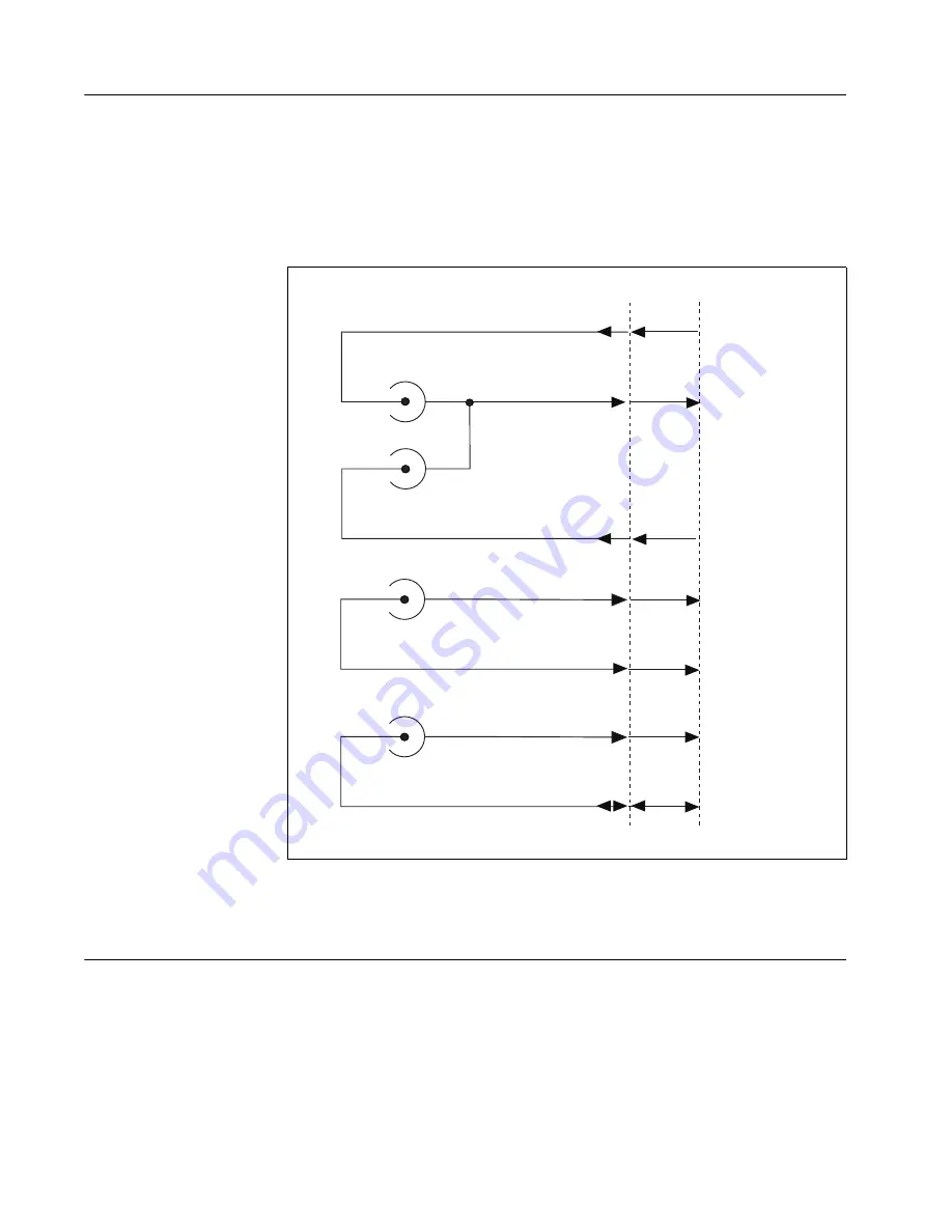
Figure 5 shows how AO 0, AO 1, APFI 0, and PFI 0 signals are routed to 
the DAQ device.

Figure 5.  

Analog Output, APFI 0, and PFI 0

Connecting Digital Signals

Use the BNC-2090A spring terminal block on the front panel to connect 
digital signals to your DAQ device. Refer to your DAQ device 
documentation for information on the use of these signals.

When connecting signals to the spring terminal blocks, you can use up to 
20 AWG wire with the insulation stripped to 0.5 in.

AO 0

DAQ Device

BNC-2090A

AO 0

AO GND

AO 1

AO 1

APFI 0

APFI 0

AI GND

PFI 0

PFI 0

D GND

Cable

Summary of Contents for BNC-2090A

Page 1: ...Refer to the BNC 2090A User Manual for in depth information about accessory installation cable connections jumper settings signals and signal conditioning as well as accessory specifications Figure 1...

Page 2: ...gure 2 Connecting the BNC 2090A to Your DAQ Device 1 Place the BNC 2090A near the host computer or mount the BNC 2090A into a 19 inch rack If you do not rack mount the accessory attach the four adhesi...

Page 3: ...ltage to within the input range of the DAQ device Input voltages greater than 42 4 Vpk 60 VDC can damage the BNC 2090A all devices connected to it and the host computer Overvoltage can also cause an e...

Page 4: ...connector below the AI 0 7 BNC connector you use 2 Move the corresponding SE DIFF switch to the DIFF position On the BNC 2090A front panel a line indicates which SE DIFF switch corresponds to each AI...

Page 5: ...sponds to each AI 0 15 BNC connector 3 Move the RSE NRSE switch to select how the ground signal is routed All single ended signals share the one RSE NRSE switch For more information about non referenc...

Page 6: ...nd PFI 0 signals are routed to the DAQ device Figure 5 Analog Output APFI 0 and PFI 0 Connecting Digital Signals Use the BNC 2090A spring terminal block on the front panel to connect digital signals t...

Page 7: ...e 6 USER 1 2 BNC Connections Figure 7 shows an example of how to use the USER 1 2 BNCs To access the PFI 5 signal from a BNC connect USER1 on the spring terminal block to PFI 5 with a wire Figure 7 Co...

Page 8: ...ion Help Patents in your software the patents txt file on your CD or ni com patents 2006 National Instruments Corporation All rights reserved 371877A 01 Dec06 Where to Go from Here Refer to the BNC 20...

Reviews: