background image

CB-27 Connector Block Installation Guide

4

ni.com

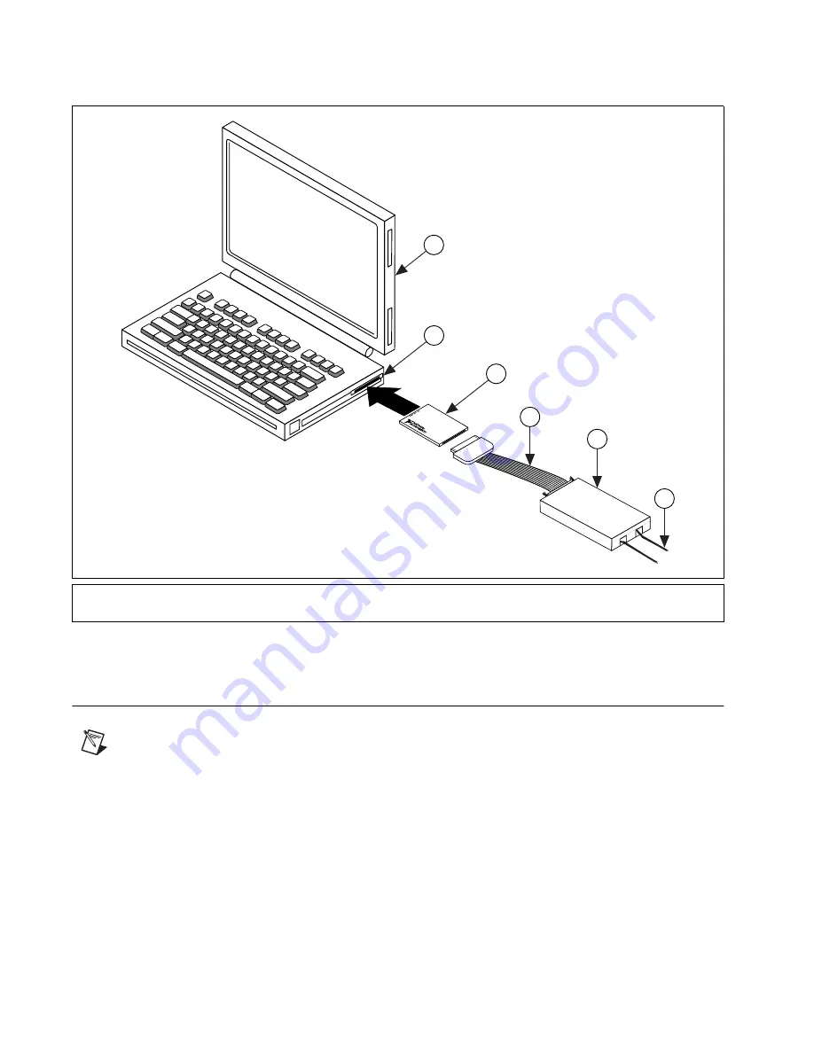
Figure 1 shows a typical configuration with the CB-27 connected to a DAQ
device and portable computer.

Figure 1.

A Typical Configuration

Connecting the Signals

Note

A blank quick-reference label, which shows the screw terminals for PCMCIA DAQ

devices, is shipped with the CB-27. You can fill in the blanks with the signal information
from the DAQ device user manual and put the label on the inside of the CB-27 cover for
easy reference. The DAQ device kit also contains a completed quick-reference label.

The NI PCMCIA-4350 kit includes a label for you to apply to the CB-27
accessory. This label provides the pin correlation between these two
devices. Table 1 shows the correlation between the screw terminals on the
CB-27 and signal names on the NI PCMCIA-4350.

1

Portable Computer

2

PCMCIA Socket

3

PCMCIA DAQ device

4

PR27-30F or PSH32-30F I/O Cable

5

CB-27

6

I/O Signals

CB-27

1

4

5

6

3

2

Summary of Contents for CB-27

Page 1: ...ay be compatible with the CB 27 Refer to the device user manual for compatibility information The CB 27 consists of a connector block with 28 screw terminals and a 30 position right angle connector wi...

Page 2: ...mming examples and syntax examples This font is also used for the proper names of disk drives paths directories programs subprograms subroutines device names functions operations variables filenames a...

Page 3: ...The PR27 30F and PSH32 30F cables are keyed so that you can insert them only one way Do not put strain on the I O cable when inserting it into and removing it from the DAQCard and the CB 27 connector...

Page 4: ...nformation from the DAQ device user manual and put the label on the inside of the CB 27 cover for easy reference The DAQ device kit also contains a completed quick reference label The NI PCMCIA 4350 k...

Page 5: ...ide Table 1 Using the PCMCIA DAQ or NI PCMCIA 4350 Device with the CB 27 PCMCIA DAQ Device Signal Name CB 27 Screw Terminal AGND 1 CH0 2 CH0 3 CH1 4 CH1 5 CH2 6 CH2 7 CH3 8 CH3 9 CH4 10 CH4 11 CH5 12...

Page 6: ...6 mm 0 25 in of the wire insulation and inserting the wires 26 18 AWG into the screw terminals Tighten the terminal screws 4 After you connect the wires to the screw terminals attach the wires to the...

Page 7: ...vice and pull it straight out If you pull the cable out using a rocking motion or pull directly on the cable you can damage the pins on the cable or on the DAQ device Remember to push on the latching...

Page 8: ...duct label or to ni com Electromagnetic Compatibility CE C Tick and FCC Part 15 Class A Compliant Electromagnetic emissions EN 55011 ISM Group I Class A at 10 m FCC Part 15A above 1 GHz Electromagneti...

Page 9: ...tion of ni com Branch office Web sites provide up to date contact information support phone numbers email addresses and current events If you have searched the technical support resources on our Web s...

Reviews: