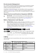

Caution
To prevent data loss and to maintain the integrity of your Ethernet
installation, do not use a cable longer than 100 m.
The first time you power up the chassis, it attempts to initiate a DHCP network connection. If
the chassis is unable to initiate a DHCP connection, it connects to the network with a link-
local IP address with the form
169.254.x.x
. After powerup, you must install software on
the chassis and configure the network settings in NI Measurement & Automation Explorer
(MAX).
Note
Installing software may change the network behavior of the chassis. For
information about network behavior by installed software version, go to
and enter the Info Code
ipconfigcrio
.
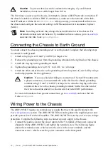
Connecting the Chassis to Earth Ground
You must connect the chassis grounding screw to earth ground. Complete the following steps
to connect to earth ground.
1.
Attach a ring lug to a 2.0 mm
2
(14 AWG) or larger wire.
2.
Remove the grounding screw from the grounding terminal on the right side of the chassis.
3.
Attach the ring lug to the grounding terminal.
4.
Tighten the grounding screw to 0.5 N · m (4.4 lb · in.) of torque.
5.
Attach the other end of the wire to the grounding electrode system of your facility using a
method appropriate for the application.
Caution
If you use shielded cabling to connect to a C Series I/O module with
a plastic connector, you must attach the cable shield to the chassis grounding
terminal using 1.3 mm
2
(16 AWG) or larger wire. Attach a ring lug to the wire
and attach the wire to the chassis grounding terminal. Solder the other end of
the wire to the cable shield. Use shorter wire for better EMC performance.
For more information about ground connections, go to
Code
emcground
.
Wiring Power to the Chassis
The cRIO-9074XT requires an external power supply that meets the specifications in the
section. The cRIO-9074XT filters and regulates the supplied power and
provides power for all of the I/O modules. The cRIO-9074XT has one layer of reverse-voltage
protection. Complete the following steps to connect a power supply to the chassis.
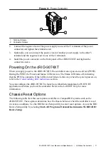
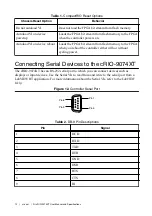
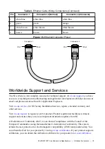
1.
Connect the positive lead of the power supply to the V terminal of the power connector
shipped with the cRIO-9074XT, and tighten the terminal screw. The following figure
shows the terminal screws, which secure the wires in the screw terminals, and the
connector screws, which secure the power connector on the front panel.
10
|
ni.com
|
NI cRIO-9074XT User Manual and Specifications