background image

drive. Refer to the 

Measurement & Automation Explorer Help

 for more information about

installing software on a controller and reformatting the drive on the controller.

CONSOLE OUT Switch

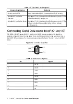
With a serial-port terminal program, you can use the CONSOLE OUT switch to read the IP
address and firmware version of the controller. Use a null-modem cable to connect the serial
port on the chassis to a computer. Push the switch to the ON position. Make sure that the
serial-port terminal program is configured to the following settings:

9,600 bits per second

Eight data bits

No parity

One stop bit

No flow control

The serial-port terminal program displays the IP address and firmware version of the chassis.
Keep this switch in the OFF position during normal operation.

IP RESET Switch

Push the IP RESET switch to the ON position and reboot the controller to reset the IP address
and other TCP/IP settings of the controller to the factory defaults. Refer to the 

Troubleshooting

Network Communication

 section for more information about resetting the IP address. You also

can push this switch to the ON position to unlock a chassis that was previously locked in
MAX.

NO APP Switch

Push the NO APP switch to the ON position to prevent a LabVIEW RT startup application
from running at startup. If you want to permanently disable a LabVIEW RT application from
running at startup, you must disable it in LabVIEW. To run an application at startup, push the
NO APP switch to the OFF position, create an application using the LabVIEW Application
Builder, and configure the application in LabVIEW to launch at startup. If you already have an
application configured to launch at startup and you push the NO APP switch from ON to OFF,
the startup application is automatically enabled. For more information about automatically
launching VIs at startup and disabling VIs from launching at startup, refer to the 

LabVIEW

Help

.

USER1 Switch

You can define the USER1 switch for your application. To define the purpose of this switch in
your embedded application, use the RT Read Switch VI in your LabVIEW RT embedded VI.
For more information about the RT Read Switch VI, refer to the 

LabVIEW Help

.

NO FPGA Switch

Push the NO FPGA switch to the ON position to prevent a LabVIEW FPGA application from
loading at startup. The NO FPGA switch overrides the CompactRIO reset options described in
the 

Chassis Reset Options

 section. After startup you can download to the FPGA from software

regardless of switch position.

14

  | 

ni.com

  | 

NI cRIO-9074XT User Manual and Specifications

Summary of Contents for CompactRIO cRIO-9074XT

Page 1: ...T SEPARATE CABLES WHEN ENERGIZED IN HAZARDOUS LOCATIONS SAFE MODE CONSOLE OUT IP RESET NO APP USER1 NO FPGA LINK LINK 10 100 10 100 RESET INPUT 19 30 V 20 W MAX TRIGGER V C NC C 1 LEDs 2 RS 232 Serial...

Page 2: ...as been switched off or the area is known to be nonhazardous Caution Do not remove modules unless power has been switched off or the area is known to be nonhazardous Caution Substitution of components...

Page 3: ...d void your authority to operate it under your local regulatory rules Special Conditions for Marine Applications Some products are Lloyd s Register LR Type Approved for marine shipboard applications T...

Page 4: ...tions Caution Your installation must meet the following requirements for space and cabling clearance Allow 25 4 mm 1 in on the top and the bottom of the chassis for air circulation Allow 50 8 mm 2 in...

Page 5: ...in 44 mm 1 73 in 23 7 mm 0 94 in 63 1 mm 2 48 in 44 1 mm 1 74 in The following sections contain instructions for the mounting methods Before using any of these mounting methods record the serial numbe...

Page 6: ...because they are the correct depth and thread for the panel Tighten the screws to a maximum torque of 1 3 N m 11 5 lb in Figure 5 Installing the Panel Mount Accessory on the cRIO 9074XT NI cR IO 9074...

Page 7: ...il Complete the following steps to mount the chassis on a DIN rail 1 Fasten the DIN rail clip to the chassis using a number 2 Phillips screwdriver and two M4 16 screws NI provides these screws with th...

Page 8: ...the mechanical dimensions of C Series I O modules Figure 9 C Series I O Module Front and Side View with Dimensions 88 1 mm 3 47 in 70 7 mm 2 78 in 22 9 mm 0 90 in Complete the following steps to inst...

Page 9: ...hat no I O side power is connected to the I O module If the system is in a nonhazardous location the chassis power can be on when you remove I O modules 2 Squeeze the latches on both sides of the modu...

Page 10: ...to the grounding electrode system of your facility using a method appropriate for the application Caution If you use shielded cabling to connect to a C Series I O module with a plastic connector you m...

Page 11: ...n The Status LED turns off indicating that the POST is complete If the LEDs do not behave in this way when the system powers on refer to the Understanding LED Indications section You can configure the...

Page 12: ...ller either with or without cycling power Connecting Serial Devices to the cRIO 9074XT The cRIO 9074XT has an RS 232 serial port to which you can connect devices such as displays or input devices Use...

Page 13: ...Info Code criosmb Configuring DIP Switches Figure 13 DIP Switches 1 6 5 4 3 2 SAFE MODE CONSOLE OUT IP RESET NO APP USER1 NO FPGA OFF All of the DIP switches are in the OFF position when the chassis...

Page 14: ...Push the NO APP switch to the ON position to prevent a LabVIEW RT startup application from running at startup If you want to permanently disable a LabVIEW RT application from running at startup you m...

Page 15: ...ED to meet the needs of your application Refer to LabVIEW Help for information about programming this LED STATUS LED The STATUS LED is off during normal operation The cRIO 9074XT indicates specific er...

Page 16: ...of your application To define the LED use the RT LEDs VI in LabVIEW For more information about the RT LEDs VI refer to the LabVIEW Help Troubleshooting Network Communication If the cRIO 9074XT cannot...

Page 17: ...unless otherwise noted Caution Do not operate the cRIO 9074XT in a manner not specified in this document Product misuse can result in a hazard You can compromise the safety protection built into the...

Page 18: ...pical input capacitance 2 5 pF Typical resistive strapping 1 k to 3 3 V Memory Nonvolatile 256 MB minimum DRAM 128 MB For information about the life span of the nonvolatile memory and about best pract...

Page 19: ...screw terminal Ferrules 0 25 mm2 to 1 5 mm2 Connector securement Securement type Screw flanges provided Torque for screw flanges 0 3 N m to 0 4 N m 2 7 lb in to 3 5 lb in Dimensions unloaded 286 4 mm...

Page 20: ...equirements of the following electrical equipment safety standards for measurement control and laboratory use IEC 61010 1 EN 61010 1 UL 61010 1 CSA 61010 1 EN 60079 0 2012 EN 60079 15 2010 IEC 60079 0...

Page 21: ...cation column Shock and Vibration To meet these specifications you must panel mount the system Operating vibration Random IEC 60068 2 64 5 grms 10 Hz to 500 Hz Sinusoidal IEC 60068 2 6 5 g 10 Hz to 50...

Page 22: ...Battery Replacement and Disposal Cd Hg Pb Battery Directive This device contains a long life coin cell battery If you need to replace it use the Return Material Authorization RMA process or contact an...

Page 23: ...t ni com services for NI Factory Installation Services repairs extended warranty and other services Visit ni com register to register your NI product Product registration facilitates technical support...

Page 24: ...cts technology refer to the appropriate location Help Patents in your software the patents txt file on your media or the National Instruments Patent Notice at ni com patents You can find information a...

Reviews: