

settings for different chassis revisions. Complete the following steps to restore the BIOS
network settings of the chassis.
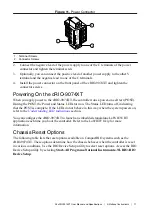
1.
Move the IP RESET and SAFE MODE switches to the ON position.
2.
Push the RESET button to cycle power to the chassis.
3.
Configure the IP and other network settings in MAX.
4.
Move the IP RESET and SAFE MODE switches to the OFF position.
Note
If the chassis is restored to the BIOS network settings, the LabVIEW
run-time engine does not load. You must reconfigure the network settings and
restart the chassis for the LabVIEW run-time engine to load.
cRIO-9074XT Specifications
The following specifications are typical for the range -40 °C to 70 °C unless otherwise noted.
Caution
Do not operate the cRIO-9074XT in a manner not specified in this
document. Product misuse can result in a hazard. You can compromise the safety
protection built into the product if the product is damaged in any way. If the product
is damaged, return it to NI for repair.
Network
Network interface
10Base-T and 100Base-TX Ethernet
Compatibility
IEEE 802.3
Communication rates
10 Mbps, 100 Mbps, auto-negotiated
Maximum cabling distance
100 m/segment
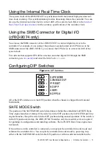
RS-232 Serial Port
Maximum baud rate
115,200 bps
Data bits
5, 6, 7, 8
Stop bits
1, 2
Parity
Odd, Even, Mark, Space
Flow control
RTS/CTS, XON/XOFF, DTR/DSR
SMB Connector
Output Characteristics
Minimum high-level output voltage
With -100 µA output current
2.9 V
With -16 mA output current
2.4 V
With -24 mA output current
2.3 V
NI cRIO-9074XT User Manual and Specifications
|
© National Instruments
|
17


