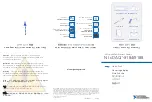
background image

Safety Guidelines

Operate the cRIO-9074XT only as described in this document.

Caution


Do not operate the cRIO-9074XT in a manner not specified in this

document. Product misuse can result in a hazard. You can compromise the safety
protection built into the product if the product is damaged in any way. If the product
is damaged, return it to NI for repair.

Safety Guidelines for Hazardous Locations

The cRIO-9074XT is suitable for use in Class I, Division 2, Groups A, B, C, D, T4 hazardous
locations; Class I, Zone 2, AEx nA IIC T4 and Ex nA IIC T4 hazardous locations; and
nonhazardous locations only. Follow these guidelines if you are installing the cRIO-9074XT in
a potentially explosive environment. Not following these guidelines may result in serious
injury or death.

Caution


Do not disconnect the power supply wires and connectors from the

controller unless power has been switched off.

Caution


Do not disconnect I/O-side wires or connectors unless power has been

switched off or the area is known to be nonhazardous.

Caution


Do not remove modules unless power has been switched off or the area is

known to be nonhazardous.

Caution


Substitution of components may impair suitability for Class I, Division 2.

Caution


For Division 2 and Zone 2 applications, install the system in an enclosure

rated to at least IP54 as defined by IEC/EN 60079-15.

Special Conditions for Hazardous Locations Use in Europe and
Internationally

The cRIO-9074XT has been evaluated as Ex nA IIC T4 Gc equipment under DEMKO
Certificate No. 12 ATEX 1202658X and is IECEx UL 14.0089X certified. Each device is
marked   II 3G and is suitable for use in Zone 2 hazardous locations, in ambient temperatures
of -40 °C ≤ Ta ≤ 70 °C.

Caution


You must make sure that transient disturbances do not exceed 140% of

the rated voltage.

Caution


The system shall only be used in an area of not more than Pollution

Degree 2, as defined in IEC 60664-1.

Caution


The system shall be mounted in an ATEX/IECEx-certified enclosure with

a minimum ingress protection rating of at least IP54 as defined in IEC/EN 60079-15.

2

  | 

ni.com

  | 

NI cRIO-9074XT User Manual and Specifications

Summary of Contents for CompactRIO cRIO-9074XT

Page 1: ...T SEPARATE CABLES WHEN ENERGIZED IN HAZARDOUS LOCATIONS SAFE MODE CONSOLE OUT IP RESET NO APP USER1 NO FPGA LINK LINK 10 100 10 100 RESET INPUT 19 30 V 20 W MAX TRIGGER V C NC C 1 LEDs 2 RS 232 Serial...

Page 2: ...as been switched off or the area is known to be nonhazardous Caution Do not remove modules unless power has been switched off or the area is known to be nonhazardous Caution Substitution of components...

Page 3: ...d void your authority to operate it under your local regulatory rules Special Conditions for Marine Applications Some products are Lloyd s Register LR Type Approved for marine shipboard applications T...

Page 4: ...tions Caution Your installation must meet the following requirements for space and cabling clearance Allow 25 4 mm 1 in on the top and the bottom of the chassis for air circulation Allow 50 8 mm 2 in...

Page 5: ...in 44 mm 1 73 in 23 7 mm 0 94 in 63 1 mm 2 48 in 44 1 mm 1 74 in The following sections contain instructions for the mounting methods Before using any of these mounting methods record the serial numbe...

Page 6: ...because they are the correct depth and thread for the panel Tighten the screws to a maximum torque of 1 3 N m 11 5 lb in Figure 5 Installing the Panel Mount Accessory on the cRIO 9074XT NI cR IO 9074...

Page 7: ...il Complete the following steps to mount the chassis on a DIN rail 1 Fasten the DIN rail clip to the chassis using a number 2 Phillips screwdriver and two M4 16 screws NI provides these screws with th...

Page 8: ...the mechanical dimensions of C Series I O modules Figure 9 C Series I O Module Front and Side View with Dimensions 88 1 mm 3 47 in 70 7 mm 2 78 in 22 9 mm 0 90 in Complete the following steps to inst...

Page 9: ...hat no I O side power is connected to the I O module If the system is in a nonhazardous location the chassis power can be on when you remove I O modules 2 Squeeze the latches on both sides of the modu...

Page 10: ...to the grounding electrode system of your facility using a method appropriate for the application Caution If you use shielded cabling to connect to a C Series I O module with a plastic connector you m...

Page 11: ...n The Status LED turns off indicating that the POST is complete If the LEDs do not behave in this way when the system powers on refer to the Understanding LED Indications section You can configure the...

Page 12: ...ller either with or without cycling power Connecting Serial Devices to the cRIO 9074XT The cRIO 9074XT has an RS 232 serial port to which you can connect devices such as displays or input devices Use...

Page 13: ...Info Code criosmb Configuring DIP Switches Figure 13 DIP Switches 1 6 5 4 3 2 SAFE MODE CONSOLE OUT IP RESET NO APP USER1 NO FPGA OFF All of the DIP switches are in the OFF position when the chassis...

Page 14: ...Push the NO APP switch to the ON position to prevent a LabVIEW RT startup application from running at startup If you want to permanently disable a LabVIEW RT application from running at startup you m...

Page 15: ...ED to meet the needs of your application Refer to LabVIEW Help for information about programming this LED STATUS LED The STATUS LED is off during normal operation The cRIO 9074XT indicates specific er...

Page 16: ...of your application To define the LED use the RT LEDs VI in LabVIEW For more information about the RT LEDs VI refer to the LabVIEW Help Troubleshooting Network Communication If the cRIO 9074XT cannot...

Page 17: ...unless otherwise noted Caution Do not operate the cRIO 9074XT in a manner not specified in this document Product misuse can result in a hazard You can compromise the safety protection built into the...

Page 18: ...pical input capacitance 2 5 pF Typical resistive strapping 1 k to 3 3 V Memory Nonvolatile 256 MB minimum DRAM 128 MB For information about the life span of the nonvolatile memory and about best pract...

Page 19: ...screw terminal Ferrules 0 25 mm2 to 1 5 mm2 Connector securement Securement type Screw flanges provided Torque for screw flanges 0 3 N m to 0 4 N m 2 7 lb in to 3 5 lb in Dimensions unloaded 286 4 mm...

Page 20: ...equirements of the following electrical equipment safety standards for measurement control and laboratory use IEC 61010 1 EN 61010 1 UL 61010 1 CSA 61010 1 EN 60079 0 2012 EN 60079 15 2010 IEC 60079 0...

Page 21: ...cation column Shock and Vibration To meet these specifications you must panel mount the system Operating vibration Random IEC 60068 2 64 5 grms 10 Hz to 500 Hz Sinusoidal IEC 60068 2 6 5 g 10 Hz to 50...

Page 22: ...Battery Replacement and Disposal Cd Hg Pb Battery Directive This device contains a long life coin cell battery If you need to replace it use the Return Material Authorization RMA process or contact an...

Page 23: ...t ni com services for NI Factory Installation Services repairs extended warranty and other services Visit ni com register to register your NI product Product registration facilitates technical support...

Page 24: ...cts technology refer to the appropriate location Help Patents in your software the patents txt file on your media or the National Instruments Patent Notice at ni com patents You can find information a...

Reviews: