Environmental Management
NI is committed to designing and manufacturing products in an environmentally responsible
manner. NI recognizes that eliminating certain hazardous substances from our products is
beneficial to the environment and to NI customers.
For additional environmental information, refer to the
Minimize Our Environmental Impact
. This page contains the environmental regulations and
directives with which NI complies, as well as other environmental information not included in
this document.
Waste Electrical and Electronic Equipment (WEEE)
EU Customers
At the end of the product life cycle, all NI products must be
disposed of according to local laws and regulations. For more information about
how to recycle NI products in your region, visit
Battery Replacement and Disposal
Cd/Hg/Pb
Battery Directive
This device contains a long-life coin cell battery. If you need to
replace it, use the Return Material Authorization (RMA) process or contact an
authorized National Instruments service representative. For more information about
compliance with the EU Battery Directive 2006/66/EC about Batteries and
Accumulators and Waste Batteries and Accumulators, visit
电子信息产品污染控制管理办法(中国
RoHS
)
中国客户
National Instruments
符合中国电子信息产品中限制使用某些有害物
质指令(
RoHS
)。关于
National Instruments
中国
RoHS
合规性信息,请登录
ni.com/environment/rohs_china
。(
For information about China RoHS
compliance, go to
ni.com/environment/rohs_china
.
)
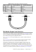
Cabling
The following table shows the standard Ethernet cable wiring connections for both normal and
crossover cables.
Table 3.
Ethernet Cable Wiring Connections
Pin
Connector 1
Connector 2 (Normal)
Connector 2 (Crossover)
1
white/orange
white/orange
white/green
2
orange
orange
green
3
white/green
white/green
white/orange
4
blue
blue
blue
22
|
ni.com
|
NI cRIO-9074XT User Manual and Specifications