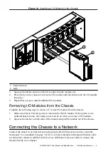
Table 3.
Ethernet Cable Wiring Connections (Continued)
Pin
Connector 1
Connector 2 (Normal)
Connector 2 (Crossover)
5
white/blue
white/blue
white/blue
6
green
green
orange
7
white/brown
white/brown
white/brown
8
brown
brown
brown
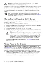
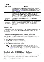
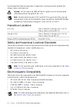
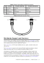
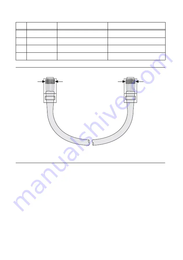
Figure 15.
Ethernet Connector Pinout
Connector 1
Connector 2
Pin 1
Pin 1
Pin 8
Pin 8
Worldwide Support and Services
The NI website is your complete resource for technical support. At
access to everything from troubleshooting and application development self-help resources to
email and phone assistance from NI Application Engineers.
Visit
for NI Factory Installation Services, repairs, extended warranty, and
other services.
Visit
to register your NI product. Product registration facilitates technical
support and ensures that you receive important information updates from NI.
A Declaration of Conformity (DoC) is our claim of compliance with the Council of the
European Communities using the manufacturer’s declaration of conformity. This system
affords the user protection for electromagnetic compatibility (EMC) and product safety. You
can obtain the DoC for your product by visiting
calibration, you can obtain the calibration certificate for your product at
NI cRIO-9074XT User Manual and Specifications
|
© National Instruments
|
23


