background image

©

 National Instruments Corporation

13

cRIO-FRC Operating Instructions and Specifications
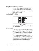
CONSOLE OUT Switch

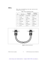
With a serial-port terminal program, you can use the CONSOLE OUT 
switch to read the IP address and firmware version of the controller. Use a 
null-modem cable to connect the serial port on the chassis to a computer. 
Push the switch to the ON position. Make sure that the serial-port terminal 
program is configured to the following settings:

9,600 bits per second

Eight data bits

No parity

One stop bit

No flow control

The serial-port terminal program displays the IP address and firmware 
version of the chassis. Keep this switch in the OFF position during normal 
operation.

IP RESET Switch

If you need to reset the IP address to the default, use the FRC cRIO Imaging 
Utility provided with the LabVIEW for FRC software. In the event that 
utility fails to restore the default IP address, you can use the IP RESET 
switch to restore it. Push the IP RESET switch to the ON position and 
reboot the chassis to reset the IP address to 

0.0.0.0

. If the chassis is on 

your local subnet and the IP RESET switch is in the ON position, the 
chassis appears in software with IP address 

0.0.0.0

NO APP Switch

Push the NO APP switch to the ON position to prevent a LabVIEW RT 
startup application from running at startup. If you want to permanently 
disable a LabVIEW RT application from running at startup, you must 
disable it in LabVIEW. To run an application at startup, push the NO APP 
switch to the OFF position, build an application in LabVIEW, and 
configure the application in LabVIEW to launch at startup. If you already 
have an application configured to launch at startup and you push the 
NO APP switch from ON to OFF, the startup application is automatically 
enabled. For more information about automatically launching VIs at startup 
and disabling VIs from launching at startup, refer to the 

LabVIEW Robotics 

Programming Guide for the FIRST Robotics Competition

.

The NO APP switch does not affect C/C++ startup applications. You can 
use the Undeploy option in Wind River Workbench to disable a C/C++ 
application.

Artisan Technology Group - Quality Instrumentation ... Guaranteed | (888) 88-SOURCE | www.artisantg.com

Summary of Contents for CompactRIO cRIO-FRC

Page 1: ...service in house repair center WE BUY USED EQUIPMENT Sell your excess underutilized and idle used equipment We also offer credit for buy backs and trade ins www artisantg com WeBuyEquipment REMOTE IN...

Page 2: ...cRIO FRC 1 LEDs 2 RS 232 Serial Port 3 RJ 45 Ethernet Port 2 4 RJ 45 Ethernet Port 1 5 Power Connector 6 Reset Button 7 DIP Switches NI cRIO FRC 1 2 4 5 6 7 POWER FPGA STATUS USER1 RESET LINK 10 100...

Page 3: ...r before installing the cRIO FRC Related Documentation To find the FIRST Robotics Competition Manual and other helpful documents mentioned in this document go to the FRC Community Web site at www usfi...

Page 4: ...g Note The cRIO FRC is shipped with slot protectors that prevent debris and contaminants from damaging the DB 15 I O module connectors in unused slots Do not remove slot protectors from unused slots F...

Page 5: ...assis before mounting it Mounting the Chassis on a Panel You can use the NI 9905 panel mount kit to mount the cRIO FRC on a flat surface Complete the following steps 1 Fasten the chassis to the panel...

Page 6: ...the wall using the screwdriver and screws that are appropriate for the wall surface Caution Make sure that no I O modules are in the chassis before removing it from the panel NI cRIO FRC 2 1 31 8 mm...

Page 7: ...e chassis on a standard 35 mm DIN rail Complete the following steps to mount the chassis on a DIN rail 1 Fasten the DIN rail clip to the chassis using a number 2 Phillips screwdriver and two M4 16 scr...

Page 8: ...efore removing it from the DIN rail Installing C Series I O Modules in the Chassis Figure 9 shows the mechanical dimensions of C Series I O modules Figure 9 C Series I O Module Front and Side View wit...

Page 9: ...nstalling an I O Module in the Chassis 3 Squeeze the latches and insert the I O module into the module slot 4 Press firmly on the connector side of the I O module until the latches lock the I O module...

Page 10: ...crossover cable to connect the chassis directly to a computer Caution To prevent data loss and to maintain the integrity of your Ethernet installation do not use a cable longer than 100 m If you need...

Page 11: ...r has been switched off Powering On the cRIO FRC When you apply power to the cRIO FRC the controller runs a power on self test POST During the POST the Power and Status LEDs turn on The Status LED tur...

Page 12: ...r Serial Port Table 1 CompactRIO Reset Options Reset Option Behavior Do Not Autoload on Reset Does not load the FPGA bit stream from flash memory Autoload on Power On Reset Loads the FPGA bit stream f...

Page 13: ...dded LabVIEW Real Time engine launches at startup If the switch is in the OFF position the LabVIEW Real Time engine launches Keep this switch in the OFF position during normal operation If the switch...

Page 14: ...e chassis to reset the IP address to 0 0 0 0 If the chassis is on your local subnet and the IP RESET switch is in the ON position the chassis appears in software with IP address 0 0 0 0 NO APP Switch...

Page 15: ...an download to the FPGA from software regardless of switch position Using the RESET Button Pressing the RESET button resets the processor in the same manner as cycling power Note The FPGA continues to...

Page 16: ...S LED flashes once indicating that the IP address is unconfigured Table 3 Status LED Indications Number of Flashes Indication 1 The chassis is unconfigured Use the cRIO FRC Imaging Utility to configur...

Page 17: ...r the LabVIEW Run Time Engine to load Specifications The following specifications are typical for the 20 to 55 C operating temperature range unless otherwise noted Network Network interface 10BaseT an...

Page 18: ...pe it with a dry towel Screw terminal wiring 0 5 to 2 5 mm2 24 to 12 AWG copper conductor wire with 10 mm 0 39 in of insulation stripped from the end Torque for screw terminals 0 5 to 0 6 N m 4 4 to 5...

Page 19: ...duct label or visit ni com certification search by model number or product line and click the appropriate link in the Certification column Electromagnetic Compatibility This product is designed to mee...

Page 20: ...l environmental information refer to the NI and the Environment Web page at ni com environment This page contains the environmental regulations and directives with which NI complies as well as other e...

Page 21: ...ction IP 40 Operating humidity IEC 60068 2 56 10 to 90 RH noncondensing Storage humidity IEC 60068 2 56 5 to 95 RH noncondensing Maximum altitude 2 000 m Pollution Degree IEC 60664 2 Shock and Vibrati...

Page 22: ...le Wiring Connections Pin Connector 1 Connector 2 Normal Connector 2 Crossover 1 white orange white orange white green 2 orange orange green 3 white green white green white orange 4 blue blue blue 5 w...

Page 23: ...port outside the United States contact your local branch office Australia 1800 300 800 Austria 43 662 457990 0 Belgium 32 0 2 757 0020 Brazil 55 11 3262 3599 Canada 800 433 3488 China 86 21 5050 9800...

Page 24: ...n are trademarks or trade names of their respective companies For patents covering National Instruments products technology refer to the appropriate location Help Patents in your software the patents...

Page 25: ...service in house repair center WE BUY USED EQUIPMENT Sell your excess underutilized and idle used equipment We also offer credit for buy backs and trade ins www artisantg com WeBuyEquipment REMOTE IN...

Reviews: