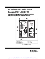

cRIO-FRC Operating Instructions and Specifications
2
ni.com
This document describes how to connect the cRIO-FRC to a network and
how to use the features of the cRIO-FRC. This document also contains
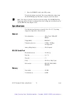
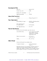
specifications for the cRIO-FRC.
What You Need to Install the cRIO-FRC
❑
FIRST
Robotics Competition kit, including cRIO-FRC reconfigurable
embedded chassis with integrated intelligent real-time controller and
the LabVIEW for FRC software
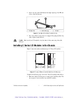
❑
C Series I/O modules
❑
DIN rail mount kit (for DIN rail mounting only)
❑
Two M4 or number 10 panhead screws (for panel mounting only)
❑
A number 2 Phillips screwdriver
❑
Power supply
Note
The cRIO-FRC may be shipped with a clear protective film cover on the front panel.
You can remove the film cover before installing the cRIO-FRC.
Related Documentation
To find the
FIRST Robotics Competition Manual
and other helpful
documents mentioned in this document, go to the FRC Community Web
site at
www.usfirst.org/community/frc
and select
Documents and
Updates
»
Competition Manual and Related Documents
.
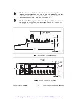
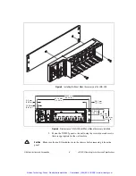
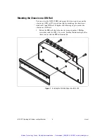
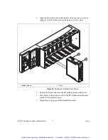
Mounting the CompactRIO Reconfigurable
Embedded Chassis
You can mount the chassis in any orientation on a 35 mm DIN rail or on a
panel. Use the DIN rail mounting method if you already have a DIN rail
configuration or if you need to be able to quickly remove the CompactRIO
chassis. Use the panel mount method for high shock and vibration
applications.
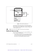
Caution
If the ambient operating temperature is 50 °C or higher, you must allow 25.4 mm
(1 in.) on the top and bottom of the chassis and in front of the I/O modules for air
circulation.
Artisan Technology Group - Quality Instrumentation ... Guaranteed | (888) 88-SOURCE | www.artisantg.com


