background image

sbRIO-96xx Features.............................................................................................................. 10

Ports and Connectors...................................................................................................... 10
RESET Button.................................................................................................................22
LEDs............................................................................................................................... 24
Internal Real-Time Clock (RTC).....................................................................................26
Real-Time Clock (RTC) Battery..................................................................................... 26

Mounting a sbRIO-960x Model..............................................................................................27

sbRIO-960x Dimensions.................................................................................................28
sbRIO-960x Mounting Direction Options...................................................................... 32

Mounting a sbRIO-962x/sbRIO-963x Model......................................................................... 34

sbRIO-962x/sbRIO-963x Dimensions............................................................................35
sbRIO-962x/sbRIO-963x Mounting Direction Options................................................. 39

Grounding the Model.............................................................................................................. 41
Connecting the sbRIO-96xx to Power.................................................................................... 42

Installing a Ferrite........................................................................................................... 43
Calculating the Power Requirement............................................................................... 44
Power-On Self Test......................................................................................................... 46

Installing Software on the Host Computer..............................................................................46
Connecting the sbRIO-96xx to the Host Computer................................................................ 47
Finding the sbRIO-96xx on the Network (DHCP)................................................................. 47
Finding the sbRIO-96xx on the Network (Static IP).............................................................. 48
Connecting CAN Networks.................................................................................................... 49

CAN Bus Topology and Termination............................................................................. 49
Cable Specifications........................................................................................................49
Termination Resistors......................................................................................................50
Cable Lengths................................................................................................................. 50
Number of CAN Nodes...................................................................................................50

Environmental.........................................................................................................................50

Managing Thermal Conditions....................................................................................... 50
Shock and Vibration........................................................................................................52
Validating the System......................................................................................................53

Troubleshooting the Controller............................................................................................... 58

The sbRIO-96xx is Not Communicating with the Network........................................... 58

Worldwide Support and Services............................................................................................ 59

CompactRIO Single-Board Controller Concepts

Table 2. System Development Manual Definitions

Term

Definition


Connector0

Connector0 refers to the MIO connector on the sbRIO-9628,
sbRIO-9629, and sbRIO-9638.

Connector1

Connector1 refers to the DIO connector on the sbRIO-9638.

2

  | 

ni.com

  | 

CompactRIO Single-Board Controller with NI-DAQmx Hardware Installation Manual

Summary of Contents for CompactRIO sbRIO-9603

Page 1: ...ngle board controller Note For information about designing systems and fixtures using the single board controller programming and configuring the single board controller and designing a RIO mezzanine card connector refer to the CompactRIO Single Board Controller with DAQmx System Development Manual on ni com manuals Table 1 CompactRIO Single Board Controller with NI DAQmx Models Digital I O Models...

Page 2: ... sbRIO 96xx on the Network DHCP 47 Finding the sbRIO 96xx on the Network Static IP 48 Connecting CAN Networks 49 CAN Bus Topology and Termination 49 Cable Specifications 49 Termination Resistors 50 Cable Lengths 50 Number of CAN Nodes 50 Environmental 50 Managing Thermal Conditions 50 Shock and Vibration 52 Validating the System 53 Troubleshooting the Controller 58 The sbRIO 96xx is Not Communicat...

Page 3: ...mx sbRIO 9628 sbRIO 9629 and sbRIO 9638 sbRIO 96xx In this document sbRIO 96xx refers exclusively to the CompactRIO single board controllers with NI DAQmx C Series Module C Series Module refers to any board only C Series module designed for implementation in an sbRIO system Onboard I O Module Onboard I O Module refers to the distinct onboard modules designed into the sbRIO 96xx sbRIO I O Module In...

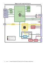
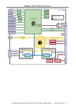
Page 4: ...N Gigabit Ethernet Port PHY USB 2 0 Device Type C Connector UART RS 232 RS 232 Console Out XCVR 5 V 3 3 V SATA 2 0 PCIe x1 Gen 2 USB 2 0 VBAT LabVIEW FPGA API Data Path Processor Data Path NI DAQmx API Data Path Power Path External Connector Port USB 3 1 Host Type C Connector Temperature Sensors Watchdog 4 GB eMMC Disk 1 GB DDR3L Power Connector 2 5 V 3 3 V Power Selector 2 5 V 3 3 V Power Selecto...

Page 5: ...rocessor Data Path NI DAQmx API Data Path Power Path USB 3 1 Host Type C Connector Battery Holder BR1632 High Speed CAN Xilinx Artix 7 75T RMC Connector 240 pin 60x4 Searay 2 5 V 3 3 V Power Selector 2 5 V 3 3 V Power Selector FPGA_VIO 0 47 Digital I O 0 47 SE LVDS Digital I O 48 95 SE LVDS FPGA_VIO 48 95 CAN Port CAN Controller 9 30 VDC Input Power Selection and Protection On board Power Supplies...

Page 6: ...hdog 4 GB eMMC Disk 2 GB DDR3L CAN Port CAN Controller 5 V 3 3 V SATA 2 0 PCIe x1 Gen 2 USB 2 0 VBAT 2 5 V 3 3 V Power Selector 2 5 V 3 3 V Power Selector FPGA_VIO 0 47 Digital I O 0 47 SE LVDS Digital I O 48 95 SE LVDS FPGA_VIO 48 95 LabVIEW FPGA API Data Path Processor Data Path NI DAQmx API Data Path Power Path External Connector Port RJ 45 TSN Gigabit Ethernet Port PHY RJ 45 TSN Gigabit Ethern...

Page 7: ...Port Connector0 MIO CAN Controller 5 V 3 3 V SATA 2 0 PCIe x1 Gen 2 USB 2 0 VBAT LabVIEW FPGA API Data Path Processor Data Path NI DAQmx API Data Path Power Path 4x Digital I O 5 V Tolerant 16x Multiplexed Analog Input 4x Analog Output 9 30 VDC Input Power Selection and Protection On board Power Supplies Power Connector Configurable per Module NI DAQmx Technology Configurable per Module NI DAQmx T...

Page 8: ...Type C Connector USB 3 1 Host Type C Connector with DisplayPort MicroSD Connector 4x Analog Output XCVR XCVR XCVR PHY PHY CAN Port Connector0 MIO CAN Controller 5 V 3 3 V PCIe x1 Gen 2 USB 2 0 Battery Holder 1632 SATA 2 0 VBAT LabVIEW FPGA API Data Path Processor Data Path NI DAQmx API Data Path Power Path FPGA_VIO 0 47 2 5 V 3 3 V Power Selector 2 5 V 3 3 V Power Selector 9 30 VDC Input Power Sel...

Page 9: ...onsole Out RS 485 RJ 45 TSN Gigabit Ethernet Port RJ 45 TSN Gigabit Ethernet Port USB 2 0 Host Type A Connector USB 2 0 Host Type A Connector USB 2 0 Device Type C Connector USB 3 1 Host Type C Connector MicroSD Connector XCVR XCVR XCVR PHY PHY CAN Port Connector1 DIO Connector0 MIO CAN Controller LabVIEW FPGA API Data Path Processor Data Path NI DAQmx API Data Path Power Path 5 V 4x Digital I O 5...

Page 10: ...1 Power terminal 2 CAN port 3 USB Type C 2 0 device port 4 USB Type C 3 1 host port with DisplayPort on the sbRIO 9609 5 RS 232 serial port with Console Out ASRL1 6 RJ 45 Gigabit Ethernet ports 7 RMC connector 10 ni com CompactRIO Single Board Controller with NI DAQmx Hardware Installation Manual ...

Page 11: ...Power 2 position 3 5 mm Mini COMBICON H 7 3 mm 0 29 in Sauro CTMH029F8 0N0LA Sauro CTF02BV8 AN000A NI 786902 01 RS 232 485 CAN IDC Header 10 pin 0 100 in CT shrouded H 9 398 mm 0 370 in Samtec TST 105 01 L D or HTST 105 01 L DV P TR TE 1658622 1 NI 10 pin to 9 pin D SUB 153158 10 50 Pin IDC Header 50 pin 2 mm CT Shrouded H 3 937 mm 0 155 in 3M 957250 6002 AR TE 2 111623 6 NI 50 position ribbon cab...

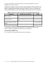
Page 12: ...in Table 4 Example Connector Configuration and Calculated Standoff Height Component Manufacturer Part Number Height RMC connector Samtec SEAF 40 06 5 S 06 2 A K TR 6 50 mm 0 256 in Mating connector Samtec SEAM 40 03 0 S 06 2 A K TR 3 00 mm 0 118 in Required additional standoff height 0 15 mm 0 006 in Total calculated standoff height 9 65 mm 0 380 in Consult Samtec for alternative heights and optio...

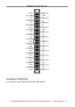
Page 13: ...10 AI11 AGND AI12 AI13 AGND AI14 AI15 AGND AGND AGND AGND AGND AGND AGND AGND AGND DGND DGND DGND DGND AI0 AGND AI1 AI2 AGND AI4 AI3 AGND AI5 AI6 AGND AGND AI7 AO0 AO1 AO2 AO3 NC NC NC NC DIO0 DIO1 DIO3 DIO2 Connector1 DIO Port Use Connector1 port for digital input output configurations CompactRIO Single Board Controller with NI DAQmx Hardware Installation Manual National Instruments 13 ...
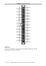
Page 14: ...ND DGND DGND DGND DGND DGND DGND DGND DGND DGND DGND DGND DGND DGND 5 V DIO4 DIO5 DIO6 DIO7 DIO8 DIO10 DIO9 DIO11 DIO12 DIO13 DIO14 DIO16 DIO15 DIO17 DIO18 DIO19 DIO20 DIO22 DIO21 DIO23 DIO24 DIO25 DIO26 5 V DIO27 CAN Port The CAN port implements a shrouded header 10 position modular jack to provide connections to a CAN or CAN FD bus 14 ni com CompactRIO Single Board Controller with NI DAQmx Hardw...

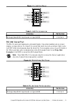
Page 15: ...n about the Serial VIs Find examples on how to use NI Serial or NI VISA to perform serial communication in the NI Example Finder Select Help Find Examples in LabVIEW to launch the NI ExampleFinder Note The ASRL1 RS 232 serial port cannot be accessed by the user application when the Console Out startup option is enabled Figure 12 RS 232 Serial Port Pinout 1 3 5 7 9 2 4 6 8 10 DCD TXD GND RTS RI RXD...

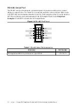
Page 16: ...mples on how to use NI Serial or NI VISA to perform serial communication in the NI Example Finder Select Help Find Examples in LabVIEW to launch the NI ExampleFinder Figure 13 RS 485 Port Pinout 1 3 5 7 9 2 4 6 8 10 GND NC RXD NC TXD NC RXD NC TXD Shield Table 7 RS 485 Serial Port Accessories Accessory Part Number NI Single Board RIO 10 pin header to 9 pin D SUB 153158 10 16 ni com CompactRIO Sing...

Page 17: ...O 960x RMC Connector Location and Dimensions 98 4 mm 3 87 in 96 7 mm 3 81 in 0 0 mm 0 00 in 0 0 mm 0 00 in 3 2 mm 0 13 in 40 0 mm 1 58 in Pin 1 CompactRIO Single Board Controller with NI DAQmx Hardware Installation Manual National Instruments 17 ...
Page 18: ...ons 98 4 mm 3 87 in 96 7 mm 3 81 in 0 0 mm 0 00 in 0 0 mm 0 00 in 3 2 mm 0 13 in 40 0 mm 1 58 in Pin 1 Caution RMCs are not hot swappable Disconnect power before mating or unmating 18 ni com CompactRIO Single Board Controller with NI DAQmx Hardware Installation Manual ...

Page 19: ...rved 27 USB_CPEN 33 GND 39 SLEEP 1 45 SLEEP 2 51 GND 57 ID_SELECT 2 63 CVRT _DIO3 2 69 GND 75 MISO_DIO6 2 81 Reserved 87 GND 93 DIO_31 DIO_31_P 99 DIO_30 DIO_31_N 105 GND 111 PCIe_Gen2 TX 3 GND 237 GND 129 DIO_27 DIO_27_P 135 DIO_26 DIO_27_N 141 GND 147 DIO_25 DIO_25_P 153 DIO_24 DIO_25_N 159 GND 165 DIO_23 DIO_23_P 171 DIO_22 DIO_23_N 177 GND 183 DIO_21 DIO_21_P 189 DIO_20 DIO_21_N 195 GND 201 DI...

Page 20: ...VIO1 Yes Yes Yes VBAT Yes Yes Yes Processor I O via DIO 0 95 CAN Yes No Not guaranteed RS 232 Yes Visit ni com r sbrio for more information Not guaranteed RS 485 Yes Not guaranteed SDHC Yes No Not guaranteed GBE_MDI 0 3 Yes No Not guaranteed USB_MODE USB_VBUS Yes No Not guaranteed USB_CPEN Yes Yes Not guaranteed Dedicated C Series DIO Yes Yes Not guaranteed VIN_FILTERED Yes Yes Yes PCIe No Yes No ...

Page 21: ...786913 01 32 GB 786989 01 USB 2 0 Type C Device Port The USB device functionality provides an alternate method to connect the controller to a host PC for configuration application deployment debugging and maintenance USB 3 1 Type C Host Port with DisplayPort Alt Mode Note The sbRIO 9609 sbRIO 9628 and sbRIO 9629 support DisplayPort Alt Mode The USB host port supports common USB mass storage device...

Page 22: ...t Ethernet Port Use the tri speed RJ 45 Gigabit Ethernet port to connect to a network or a host computer By default the Ethernet port is enabled and configured to obtain an IP address automatically The Ethernet port can be configured in MAX Note Both Ethernet ports perform automatic crossover configuration so you do not need to use a crossover cable to connect to a host computer Table 13 RJ 45 Gig...

Page 23: ...d RESET button for 5 s Run Mode Safe Mode Press and hold RESET button for 5 s Press and hold RESET button for 5 s Press and hold RESET button for 5 s Press and hold RESET button for 5 s Console Out enabled Network settings reset RT Startup App disabled FPGA Startup App disabled Console Out enabled RT Startup App disabled FPGA Startup App disabled Safe Mode CompactRIO Single Board Controller with N...

Page 24: ...r LED 2 Status LED 3 User1 LED 4 User FPGA1 LED 5 SD In USE LED POWER LED Indicators Table 14 POWER LED Indicators LED Color LED Pattern Indication Green Solid The sbRIO 96xx is powered ON or powered through the RMC connector Off The sbRIO 96xx is powered OFF 24 ni com CompactRIO Single Board Controller with NI DAQmx Hardware Installation Manual ...

Page 25: ...to boot into safe mode by pressing the reset button for longer than five seconds or by enabling safe mode in MAX Refer to the Measurement Automation Explorer MAX Help for information about safe mode Blinks four times and pauses The sbRIO 96xx is in safe mode The software has crashed twice without rebooting or cycling power between crashes Continuously blinks The sbRIO 96xx has not booted into NI L...

Page 26: ... selected Internal Real Time Clock RTC The system clock of the NI sbRIO 96xx gets the date and time from the internal RTC at startup This synchronization provides timestamp data to the device Real Time Clock RTC Battery The sbRIO 96xx contains an RTC battery which is a lithium cell battery that stores the system clock information when the sbRIO 96xx is powered off Only a slight drain on the RTC ba...

Page 27: ...site regulations For more information about disposing of or recycling this device s battery refer to https www rayovac com Mounting a sbRIO 960x Model You can mount the NI sbRIO device in a variety of ways in order to maximize system performance Some mounting methods might require custom fasteners or unique assembly techniques to maintain required connector stack heights and enable improved therma...

Page 28: ...89 in Pin 1 80 8 mm 3 18 in 76 7 mm 3 02 in NAND Flash CPU 46 2 mm 1 82 in 38 7 mm 1 53 in USB PHY 24 9 mm 0 98 in ENET 1210 0 0 mm 0 00 in 73 2 mm 2 88 in 51 8 mm 2 04 in 28 4 mm 1 12 in 15 4 mm 0 61 in 5 4 mm 0 21 in 0 0 mm 0 00 in 84 6 mm 3 33 in 79 4 mm 3 13 in FPGA 65 5 mm 2 58 in 55 0 mm 12 16 in 43 2 mm 1 70 in NI ASIC 2 8 1 mm 0 32 in 24 2 mm 0 95 in Pin 2 28 ni com CompactRIO Single Board...

Page 29: ... 0 0 mm 0 00 in 3 2 mm 0 13 in 40 0 mm 1 58 in 43 8 mm 1 73 in 76 8 mm 3 03 in 96 5 mm 3 80 in 71 7 mm 2 82 in 102 9 mm 4 05 in 73 6 mm 2 90 in Note Holes and keepouts are sized for M3 standoff 4 5 mm Hex or 4 40 standoff 3 16 in Hex CompactRIO Single Board Controller with NI DAQmx Hardware Installation Manual National Instruments 29 ...

Page 30: ...39 7 mm 1 56 in 2 6 mm 0 10 in 5 3 mm 0 21 in 10 6 mm 0 42 in Tip For two dimensional drawings and three dimensional models of the sbRIO 960x visit ni com dimensions and search by model number sbRIO 960x Maximum Component Heights Note In addition to the maximum component heights you must also observe minimum keepaway distances for adjacent PCBs and surfaces 30 ni com CompactRIO Single Board Contro...

Page 31: ...ight 7 1 mm 0 28 in Minimum Adjacent Surface Height 8 9 mm 0 35 in Maximum Component Height 17 3 mm 0 68 in Minimum Adjacent Surface Height 19 1 mm 0 75 in 31 8 mm 1 25 in CompactRIO Single Board Controller with NI DAQmx Hardware Installation Manual National Instruments 31 ...

Page 32: ... Adjacent Surface Height 7 6 mm 0 30 in 11 4 mm 0 45 in 61 0 mm 2 40 in sbRIO 960x Mounting Direction Options The Thermal Kit for CompactRIO Single Board Controller with NI DAQmx 787331 01 and certain RMC accessories are designed to allow traditional M F standoff threads to pass through and stack in either direction 32 ni com CompactRIO Single Board Controller with NI DAQmx Hardware Installation M...

Page 33: ... 5 6 3 4 1 2 1 Exploded view of all mounting components 2 Complete assembled and mounted view 3 Mounting screws 4 Standoff 9 65 mm 0 38 in 5 Standoff 16 0 mm 0 63 in 6 Thermal Kit for CompactRIO Single Board Controller with NI DAQmx 787331 01 7 RMC board 8 NI sbRIO 9603 9608 9609 9 Thermal pad main Included with the Thermal Kit 10 Thermal pad supplemental sbRIO 9603 only Included with the Thermal ...

Page 34: ...IO Single Board Controller with NI DAQmx 787331 01 5 Standoff 16 0 mm 0 63 in 6 NI sbRIO 9603 9608 9609 7 RMC board 8 Mounting screws 9 Thermal pad supplemental sbRIO 9603 only Included with the Thermal Kit 10 Thermal pad main Included with the Thermal Kit 11 Standoff 9 65 mm 0 38 in 12 Standoff 13 Mounting surface Mounting a sbRIO 962x sbRIO 963x Model You can mount the NI sbRIO device in a varie...

Page 35: ...8 in 76 7 mm 3 02 in NAND Flash CPU 46 2 mm 1 82 in 38 7 mm 1 53 in USB PHY 24 9 mm 0 98 in ENET 1210 0 0 mm 0 00 in 73 2 mm 2 88 in 51 8 mm 2 04 in 28 4 mm 1 12 in 15 4 mm 0 61 in 5 4 mm 0 21 in 0 0 mm 0 00 in 84 6 mm 3 33 in 79 4 mm 3 13 in FPGA 65 5 mm 2 58 in 55 0 mm 12 16 in 43 2 mm 1 70 in NI ASIC 2 8 1 mm 0 32 in 24 2 mm 0 95 in DDR Memory CPLD NI ASIC 1 75T 200T Pin 2 OSC 17 1 mm 0 65 in 1...

Page 36: ...2 90 in 73 6 mm 2 90 in 0 0 mm 0 00 in 3 2 mm 0 13 in 40 0 mm 1 58 in 43 8 mm 1 73 in 76 8 mm 3 03 in 153 7 mm 6 05 in 150 5 mm 5 92 in 71 7 m 2 82 in 102 9 mm 4 05 in Note Holes and keepouts are sized for M3 standoff 4 5 mm Hex or 4 40 standoff 3 16 in Hex 36 ni com CompactRIO Single Board Controller with NI DAQmx Hardware Installation Manual ...
Page 37: ...4 7 mm 2 55 in 55 7 mm 2 19 in 48 7 mm 1 92 in 33 8 mm 1 33 in 39 7 mm 1 56 in 2 6 mm 0 10 in Tip For two dimensional drawings and three dimensional models of the sbRIO 962x sbRIO 963x visit ni com dimensions and search by model number sbRIO 962x sbRIO 963x Maximum Component Heights Note In addition to the maximum component heights you must also observe minimum keepaway distances for adjacent PCBs...

Page 38: ...Height 8 9 mm 0 35 in Maximum Component Height 9 5 mm 0 38 in Minimum Adjacent Surface Height 9 5 mm 0 38 in 96 5 mm 3 80 in Maximum Component Height 17 3 mm 0 68 in Minimum Adjacent Surface Height 19 1 mm 0 75 in 31 8 mm 1 25 in 38 ni com CompactRIO Single Board Controller with NI DAQmx Hardware Installation Manual ...
Page 39: ...mum Adjacent Surface Height 7 6 mm 0 30 in 61 0 mm 2 40 in sbRIO 962x sbRIO 963x Mounting Direction Options The Thermal Kit for CompactRIO Single Board Controller with NI DAQmx 787331 01 and certain RMC accessories are designed to allow traditional M F standoff threads to pass through and stack in either direction CompactRIO Single Board Controller with NI DAQmx Hardware Installation Manual Nation...
Page 40: ...8 9 5 6 3 4 1 2 1 Exploded view of all mounting components 2 Complete assembled and mounted view 3 Mounting screws 4 Standoff 9 65 mm 0 38 in 5 Standoff 16 0 mm 0 63 in 6 Thermal Kit for CompactRIO Single Board Controller with NI DAQmx 787331 01 7 RMC board 8 NI sbRIO 9628 9629 9638 9 Thermal pad main Included with the Thermal Kit 10 Thermal pad supplemental sbRIO 9628 9638 only Included with the ...

Page 41: ... Heatsink 4 Thermal Kit for CompactRIO Single Board Controller with NI DAQmx 787331 01 5 Standoff 16 0 mm 0 63 in 6 NI sbRIO 9628 9629 9638 7 RMC board 8 Mounting screws 9 Thermal pad supplemental sbRIO 9628 9638 only Included with the Thermal Kit 10 Thermal pad main Included with the Thermal Kit 11 Standoff 9 65 mm 0 38 in 12 Standoff 13 Mounting surface Grounding the Model You can terminate a gr...

Page 42: ...raversing through the NI sbRIO 96xx can result in device failure To verify correct grounding of the NI sbRIO 96xx make sure the current flowing into the power connector equals the current flowing out of the power connector These currents should be measured with a current probe after final assembly of the end system Investigate and remove any current differences Connecting the sbRIO 96xx to Power T...

Page 43: ...r power supply is powered off 2 Insert the power connector plug into the power connector receptacle of the NI sbRIO 96xx until the connector latches into place 3 Turn on the power supply Installing a Ferrite What to Use Ferrite NI part number 711849 01 included in kit Screwdriver 2 54 mm 0 10 in flathead Primary power supply 9 V to 30 V 55 W minimum What to Do Complete the following steps to insta...

Page 44: ...the 5 V voltage output across the RMC or DIO connectors P3 3V is the power consumption by the 3 3 V voltage output across the RMC connector PµSD is the power consumption of a MicroSD card installed in the MicroSD port PUSB Type C is the power consumption of a device plugged into the USB Type C port PUSB 2 0 is the power consumption of a device plugged into the USB 2 0 port PETH is 0 4 W typical pe...

Page 45: ...VDS sbRIO 960x and sbRIO 962x Number of RMC LVDS outputs 0 0395 W maximum of 45 outputs PµSD sbRIO 962x and sbRIO 963x Total µSD current 3 3 V 0 8 1 4 A maximum 0 5 A typical PUSB Type C All sbRIO 96xx Total USB current 5 V 0 9 0 9 A maximum 0 25 A typical for flash drive 0 5 A typical for display PUSB 2 0 sbRIO 962x and sbRIO 963x Total USB current 5 V 0 9 1 4 A maximum 0 25 A typical for flash d...

Page 46: ...mptions include 85 LUT Flip Flop DSP BRAM utilization of the FPGA running at 80 MHz and 100 processor utilization Power On Self Test The NI sbRIO 96xx runs a power on self test POST when you apply power to the device The Power and Status LEDs turn on when the POST begins The Status LED turns off when the POST completes Note Refer to the STATUS LED Indicators section to troubleshoot Status LED beha...

Page 47: ... connection it connects to the network with a link local IP address with the form 169 254 x x After the device has powered up you must install software on the device and configure the network settings in MAX Note Installing software may change the network behavior of the device For information about network behavior by installed software version visit ni com r ipconfigcrio Finding the sbRIO 96xx o...

Page 48: ...the network settings of the host computer Tip You can also access these settings by opening the Start menu entering cmd exe and entering ipconfig in the command window that launches g Wait at least one minute 2 Configure IP Settings on the controller in MAX a Launch MAX on the host computer b Expand Remote Systems in the configuration tree and locate your system Note MAX lists the system under the...

Page 49: ... main CAN bus cable through a short connection called a stub The pair of signal wires CAN_H and CAN_L constitutes a transmission line If the transmission line is not terminated signal changes on the bus cause reflections that can cause communication errors The CAN bus is bidirectional and both ends of the cable must be terminated However only the two nodes at the far end of the cable not every nod...

Page 50: ...h of 0 3 m for a bit rate of 1 Mb s The ISO 11898 specification allows for significantly longer cable lengths at lower bit rates but NI recommends that you analyze each node for signal integrity problems Number of CAN Nodes The maximum number of nodes depends on the electrical characteristics of the nodes on the network If all nodes meet the ISO 11898 requirements you can connect at least 30 nodes...

Page 51: ...be 85 C In this way properly designed NI sbRIO 96xx may still require an external ambient temperature of 70 C or less and may still require specific mounting requirements to ensure that the local ambient and thermally relevant component maximum operating temperatures are within specification Understanding Thermal Specifications A deployed system has several temperature measurement locations that i...

Page 52: ...system integrator may use any number of enclosure sizes materials thermal solutions and room conditions when designing an enclosure for a specific application sbRIO 96xx are specified in a manner that removes most of these external variables Therefore the sbRIO 96xx thermal performance is not determined by measuring the external ambient or internal enclosure ambient temperatures but by measuring t...

Page 53: ...ance during validation and deployment The sensors measure the CPU FPGA junction temperature and printed circuit board temperatures that can be used to approximate the primary and secondary side local ambient temperatures This approach is called digital validation Alternatively the traditional analog approach using thermocouples can be used to validate thermal performance The digital approach is mo...

Page 54: ... 96xx consumes when running your application in an environment that is representative of the intended use case Mounting Recommendations for Maximizing Thermal Performance Thermal performance of the sbRIO 96xx can be maximized by implementing the following recommendations Directly mount a thermal solution such as the Thermal Kit for CompactRIO Single Board Controller with NI DAQmx 787331 01 to a th...

Page 55: ...DAQmx 787331 01 does not satisfy your design requirements NI recommends replicating the features of the heat spreader into your own thermal solution Use the specified pedestal dimensions and a Laird HD700 0 060 in thermal gap pad with a fastener assembly rate of 4 23 mm s 10 in min to prevent damage to the critical components during assembly NI recommends that you replicate each of the pedestals a...

Page 56: ...2 in 30 8 mm 1 21 in 35 2 mm 1 39 in 15 6 mm 0 61 in 17 6 mm 0 69 in 96 6 mm 3 68 in 75 6 mm 2 98 in 77 8 mm 3 06 in 67 8 mm 2 67 in 62 0 mm 2 44 in 33 4 mm 1 31 in 48 0 mm 1 89 in 8 4 mm 0 33 in 10 2 mm 0 42 in 2 4 mm 0 10 in 0 0 mm 0 00 in A B J I H G F E D C Table 22 Pedestal Height from Board Surface Designation Pedestal Corresponding Component Pedestal Height from Board Surface2 A FPGA 75T 2 ...

Page 57: ...confined to within the indicated region are allowed to violate the primary side maximum component height keepaway restrictions Note Pedestals of the same dimensions are allowed to have 0 5 mm 0 02 in rounds and 2 draft angles Additional Resources for Managing Thermal Conditions Visit ni com r sbriocooling for the following additional information to help you manage thermal conditions Examples regar...

Page 58: ...rnet port 0 or port 1 to reconnect the sbRIO 96xx to the host computer The sbRIO 96xx attempts to initiate a DHCP network connection at power up Note If the sbRIO 96xx cannot obtain an IP address it connects to the network with a link local IP address with the form 169 254 x x The host computer communicates with the sbRIO 96xx over a standard Ethernet connection Ensure that you have the correct ve...

Page 59: ...you sbRIO 96xx can communicate with the network Use the Troubleshoot Remote System Discovery tool to configure the firewall 1 In MAX right click Remote Systems and select Troubleshoot Remote System Discovery 2 Follow the steps in the tool Add an exception for MAX to your network firewall or other security software by completing the following steps 1 Select Start Control Panel Windows Firewall Allo...

Page 60: ...ioned herein are trademarks or trade names of their respective companies For patents covering NI products technology refer to the appropriate location Help Patents in your software the patents txt file on your media or the National Instruments Patent Notice at ni com patents You can find information about end user license agreements EULAs and third party legal notices in the readme file for your N...

Reviews: