•
Module Immobilization accessory kit, 158534-01
–
Module immobilization bracket
–
Installation screws
1
•
M4 x 0.7 button-head screw, 8 mm
•
M3 x 0.5 flat-head screws (x2), 10 mm
•
Torx T10/T10H driver
•
Torx T20/T20H driver
What to Do
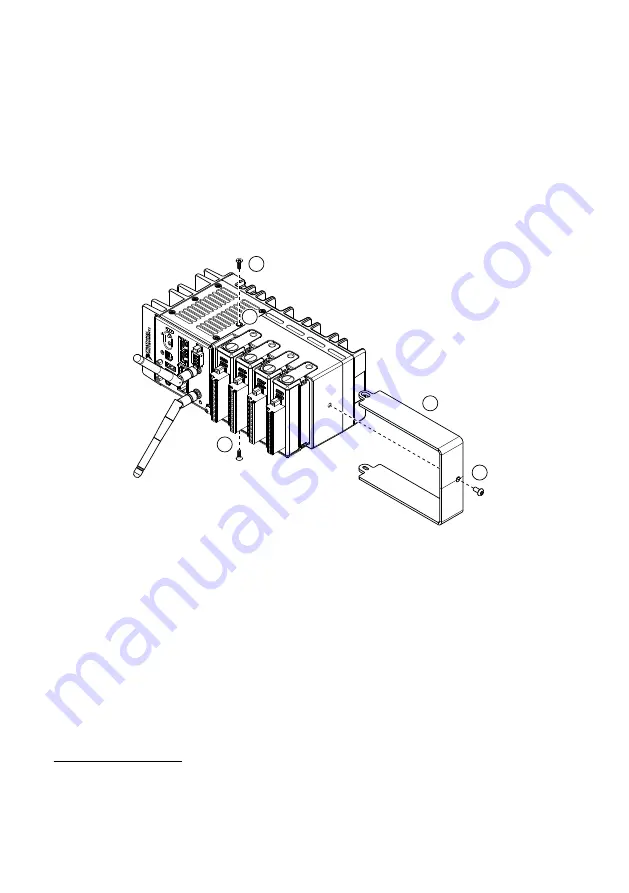
Complete the following steps to install the Module Immobilization accessory.
1
2
5
3
4
1.
Ensure that all the C Series modules are installed in the cRIO-9032 and the latches are
locked in place.
2.
Remove the center right panel screw from the top and bottom of the cRIO-9032 using the
Torx T10 driver.
3.
Slide the bracket into place, aligning the three clearance screw holes.
4.
Install the M4 x 0.7 button-head screw in the right end of the cRIO-9032 using the
appropriate Torx T20 driver. Tighten the screw to a maximum torque of 1.3 N · m
(11.5 lb · in.).
1
The Module Immobilization accessory kit includes two sets of screws. One set is a standard set of
screws that require a standard driver type, Torx T10 and T20. The other set is a tamper-resistant set
of screws that require a security driver type, Torx T10H and T20H. Use the tamper-resistant set to
help prevent unintended modification of the system.
NI cRIO-9032 User Manual
|
© National Instruments
|
23


