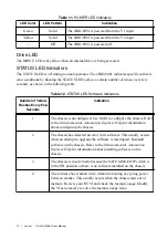

Table 14.
User LEDs
LED
LED Color
Description
USER1
Green/Yellow Use LabVIEW Real-Time to define the USER1 LED with the
RT LEDs VI. For more information about the RT LEDs VI,
refer to the
LabVIEW Help
.
USER
FPGA1
Green/Yellow Use the LabVIEW FPGA Module and NI-RIO Device
Drivers software to define the USER FPGA1 LED. Use the
USER FPGA1 LED to help debug your application or retrieve
application status. Refer to the
LabVIEW Help
for information
about programming this LED.
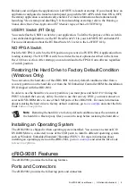
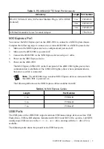
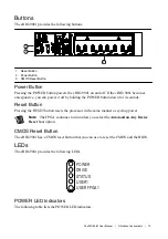
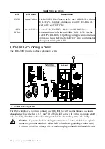
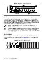
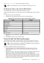
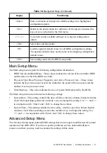
Chassis Grounding Screw
The cRIO-9081 provides a chassis grounding screw.
NI cRIO-9081
1
1. Chassis Grounding Screw
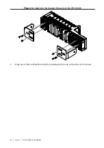
For EMC compliance, you must connect the cRIO-9081 to earth ground through the chassis
ground screw. Use wire that is 1.31 mm
2
(16 AWG) solid copper wire with a maximum length
of 1.5 m (5 ft). Attach the wire to the earth ground of the electrode system of the facility.
Caution
If you use shielded cabling to connect to a C Series module with a plastic
connector, you must attach the cable shield to the chassis grounding terminal using
1.31 mm
2
(16 AWG) or larger wire. Attach a ring lug to the wire and attach the wire
16
|
ni.com
|
NI cRIO-9081 User Manual


