background image

DISABLE RT Switch

The position of the DISABLE_RT determines the operating system the controller boots into. If
the switch is in the OFF position, the system boots into LabVIEW RT. If the switch is the ON
position, the system boots into the non-RT OS installed on the system, such as Windows.

SAFE MODE Switch (RT Only)

The position of the SAFE MODE switch determines whether the embedded LabVIEW Real-
Time engine launches at startup. If the switch is in the OFF position, the LabVIEW Real-Time
engine launches. Keep this switch in the OFF position during normal operation. If the switch is
in the ON position at startup, the cRIO-9081 launches only the essential services required for
updating its configuration and installing software. The LabVIEW Real-Time engine does not
launch.

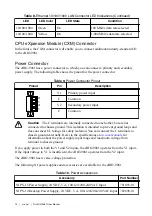
CONSOLE OUT Switch (RT Only)

The position of the CONSOLE OUT switch determines whether console input and output are
redirected to the RS-232 serial port. If the switch is in the ON position, console input and
output are redirected to the RS-232 serial port. If the switch is in the OFF position, the RS-232
serial port functions normally.

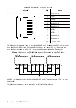
With a serial-port terminal program, you can use console output to read the POST results,
BIOS revision, IP addresses, and software installed on the cRIO-908x. You can also enter the
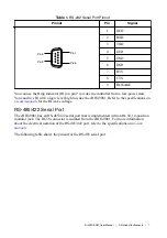
BIOS setup menu and modify BIOS settings. Use a null-modem cable to connect the RS-232
serial port on the chassis to a computer. Push the CONSOLE OUT switch to the ON position.
Make sure that the serial-port terminal program is configured with the same settings as the
RS-232 serial port. The default configuration settings for the RS-232 serial port in CONSOLE
OUT mode are the following:

9,600 bits per second

Eight data bits

No parity

One stop bit

No flow control

You can use the BIOS setup menu to modify the CONSOLE OUT configuration settings for
the RS-232 serial port.

Keep the CONSOLE OUT switch in the OFF position during normal operation.

IP RESET Switch (RT Only)

Push the IP RESET switch to the ON position and reboot the controller to reset the IP address
and other TCP/IP settings of the controller to the factory defaults. You can also push this
switch to the ON position to unlock a controller that was previously locked in MAX.

NO APP Switch (RT Only)

Push the NO APP switch to the ON position to prevent a LabVIEW RT startup application
from running at startup. If you want to permanently disable a LabVIEW RT application from
running at startup, you must disable it in LabVIEW. To run an application at startup, push the
NO APP switch to the OFF position, create an application using the LabVIEW Application

4

  | 

ni.com

  | 

NI cRIO-9081 User Manual

Summary of Contents for cRIO-9081

Page 1: ...mation about mounting and operating the device USB 2 0 Host Port USB 2 0 Host Port RJ 45 Gigabit Ethernet Port 1 2 GB DDR3 16 GB CFast SSD RS 232 Serial Port RJ 50 RS 485 422 DTE Serial Port MXI Expre...

Page 2: ...connects to the network with a link local IP address with the form 169 254 x x if it is unable to initiate a DHCP connection Finding the cRIO 9081 on the Network DHCP Complete the following steps to f...

Page 3: ...the system under the model number followed by the serial number such as NI cRIO 9081 1856AAA c Select the Network Settings tab near the bottom of the window d Select Static on the Configure IPv4 Addr...

Page 4: ...sses and software installed on the cRIO 908x You can also enter the BIOS setup menu and modify BIOS settings Use a null modem cable to connect the RS 232 serial port on the chassis to a computer Push...

Page 5: ...of the cRIO 9081 to factory default condition either from a recovery partition on the hard drive or from the NI Embedded Controller OEM Re Installation DVD shipped with thecRIO 9081 In order to use t...

Page 6: ...RS 232 Serial Port RS 232 Serial Port The cRIO 9081 has an RS 232 serial port to which you can connect devices such as displays or input devices Use the Serial VIs to read from and write to the serial...

Page 7: ...81 Refer to the specifications on ni com manuals for the RI wake voltage RS 485 422 Serial Port The cRIO 9081 has an RS 485 422 serial port that is implemented with an RJ 50 10 position modular jack T...

Page 8: ...9081 Only two FP 1001 banks are shown but the cRIO 9081 can control up to 24 nodes Install 120 termination resistors at each end of the network Figure 2 Wiring for an RS 485 422 Network Controlled by...

Page 9: ...on the cRIO 9081 The MXI Express LINK LED on the front panel of the cRIO 9081 lights green when communication is established The LINK LED lights yellow when communication is broken or no cable is con...

Page 10: ...ists the VGA signals Pin Signal Name Signal Description 1 RED Red analog video signal 2 GREEN Green analog video signal 3 BLUE Blue analog video signal 4 NC No Connect 5 GND Ground reference 6 RED RET...

Page 11: ...RX_D 7 No Connect RX_D 8 Note Both Ethernet ports perform automatic crossover configuration so you do not need to use a crossover cable to connect to a host computer The following NI Ethernet cables...

Page 12: ...nected to each other but are not connected to chassis ground This isolation is intended to prevent ground loops and does not meet UL ratings for safety isolation You can connect the C terminals to cha...

Page 13: ...Reset Button Pressing the RESET button resets the processor in the same manner as cycling power Note The FPGA continues to run unless you select the Autoload on Any Device Reset boot option CMOS Rese...

Page 14: ...is is unconfigured Use MAX to configure the chassis Refer to the Measurement Automation Explorer Help for information about configuring the chassis 2 The chassis has detected an error in its software...

Page 15: ...shown in the following table Table 13 STATUS LED Hardware Indicators Pattern of Red Flashes Indication Continuously Flashing An internal power supply has failed Check front panel I O CXM and C Series...

Page 16: ...LED Chassis Grounding Screw The cRIO 9081 provides a chassis grounding screw NI cRIO 9081 1 1 Chassis Grounding Screw For EMC compliance you must connect the cRIO 9081 to earth ground through the cha...

Page 17: ...power is applied to the cRIO 9081 power connector The rate at which the CMOS battery drains when power is disconnected depends on the ambient storage temperature For longer battery life store the cRI...

Page 18: ...nfigurations visit ni com info and enter the Info Code criotypical Caution Make sure that no C Series modules are in the cRIO 9081 before mounting it Tip Before using any of these mounting methods rec...

Page 19: ...IO 9081 for air circulation as shown in the following figure Figure 6 cRIO 9081 Cooling Dimensions Cooling Outline 50 8 mm 2 00 in Cooling Outline 50 8 mm 2 00 in 88 1 mm 3 43 in NI cRIO 9081 Allow th...

Page 20: ...9081 Ambient Temperature Location 50 8 mm 2 00 in 63 5 mm 2 50 in 50 8 mm 2 00 in 63 5 mm 2 50 in 1 1 1 Location for measuring the ambient temperature Mounting the Device Directly on a Flat Surface Fo...

Page 21: ...ed 8 mm of insertion into the cRIO 9081 Tighten the screws to a maximum torque of 1 3 N m 11 5 lb in Surface Mounting Dimensions The following figure shows the surface mounting dimensions for the cRIO...

Page 22: ...e 2 Fasten the panel mounting plate to the cRIO 9081 using the screwdriver and M4x10 screws NI provides these screws with the panel mounting kit Tighten the screws to a maximum torque of 1 3 N m 11 5...

Page 23: ...3 mm 4 50 in 188 6 mm 7 43 in 2 5 mm 0 10 in 108 9 mm 4 29 in 58 2 mm 2 29 in 25 4 mm 1 00 in 108 9 mm 4 29 in NI cRIO 9081 Mounting the Device on a DIN Rail You can use the NI DIN rail mounting kit t...

Page 24: ...h and thread for the DIN rail clip Clipping the Device on a DIN Rail Complete the following steps to clip the cRIO 9081 on a DIN rail 1 2 1 Insert one edge of the DIN rail into the deeper opening of t...

Page 25: ...he NI Desktop Mount Kit 1 2 3 1 Desktop mounting brackets x2 2 Adapter brackets x2 3 M4x10 screws x6 What to Do Complete the following steps to mount the cRIO 9081 on a desktop 1 Use a 1 Phillips scre...

Page 26: ...Figure 12 Attaching the Adapter Brackets to the cRIO 9081 2 Align one of the end brackets with the mounting hole at one of the ends of the chassis 26 ni com NI cRIO 9081 User Manual...

Page 27: ...e end bracket 4 Repeat steps 2 and 3 to attach the other end bracket to the other end of the chassis Desktop Mounting Dimensions The following figures show the desktop mounting dimensions for the cRIO...

Page 28: ...attery to preserve the settings Additionally the BIOS optimizes boot time by saving specific system information to memory backed up by a battery CMOS Complete the following steps to reset the CMOS and...

Page 29: ...OST displays warning messages for specific issues onscreen You can use MAX to enable Console Out to send these warning messages through the RS 232 serial port Note When a warning message is displayed...

Page 30: ...havior including failure to boot In general do not change a setting unless you are sure what the setting does Reset the BIOS settings to restoring the default configuration settings Launching the BIOS...

Page 31: ...ore These values indicate the type of processor used in the controller the speed of the processor and the number of active processor cores Total Memory This value indicates the size of system RAM dete...

Page 32: ...the SATA port Some operating systems such as Windows 2000 do not support AHCI mode You can use this setting to disable AHCI mode and enable IDE mode so that non compatible OSes function correctly The...

Page 33: ...esponds to the power button as defined by the OS If the value is Disabled pressing the power button has no effect when the system is on When the system is in the soft off state pushing the power butto...

Page 34: ...This setting enables the Intel Management Engine Setup prompt during the POST If this setting is enabled pressing CTRL P during the POST starts the ME Setup utility The default value is Disabled Unco...

Page 35: ...he default value is None Stop Bits This setting selects the number of stop bits Valid values are 1 and 2 The default value is 1 Flow Control This setting enables flow control to help prevent data loss...

Page 36: ...hen booting LabVIEW RT The default value is Use RT Default Boot Setup Menu The Boot Setup menu contains setting related to the boot process and the boot device priority Boot Settings Configuration Sub...

Page 37: ...s the Network Device BBS Priorities submenu to re order or disable bootable network devices Boot Settings Configuration Submenu The Boot Settings Configuration submenu applies alternate configurations...

Page 38: ...at must be entered to access the BIOS Setup Utility or to boot the system If only the User s password is set then this is a power on password and must be entered to boot or enter the BIOS setup utilit...

Page 39: ...you have access to everything from troubleshooting and application development self help resources to email and phone assistance from NI Application Engineers Visit ni com services for NI Factory Inst...

Page 40: ...party legal notices in the readme file for your NI product Refer to the Export Compliance Information at ni com legal export compliance for the NI global trade compliance policy and how to obtain rel...

Reviews: